The Hydrodynamic Equations
The Hydrodynamic Equations of Motion in a Fixed and in a Rotating Coordinate System. One of the fundamental laws of mechanics states that the acceleration of a body equals the sum of the forces per unit mass acting on the body. This law is applicable not only to individual bodies but also to every part of a fluid. The hydrodynamic equations of motion express only this simple principle, but, when dealing with a fluid, not only the equations of motion must be satisfied, but also the equation of continuity and the proper dynamic and kinematic boundary conditions.
The hydrodynamic equations of motion as developed by Euler take into account two forces only: an external force acting on a unit mass, and the total pressure gradients per unit mass. If the components of the
In this form or in the form obtained by substituting equation (XII, 17) for dv/dt, the equations represent the basis of classical hydrodynamics and have been used extensively for the study of many types of fluid motion. The only external force that needs to be considered in these cases is the acceleration of gravity. If the coordinate system is placed with the xy plane coinciding with a level surface, the equation takes an especially simple form, because the horizontal components of the external force vanish and the vertical is equal to g:
In many problems, friction must be considered, and to each equation a term must be added to represent the components of the frictional force.
The coordinate system used in these cases is rigidly connected with the earth and therefore takes part in the earth's rotation. When, for example, the flow through a pipe is analyzed, the x axis is placed in the direction of the pipe. This procedure is justified on the empirical basis that the observed motion can be correctly described in this manner. This fact, and only this fact, made possible the development of the Galileo-Newton mechanic. Phenomena exist, however, which cannot be adequately described by means of the simple equations of motion if accurate observations are made, as, for instance, the free fall of a body or the exact oscillation of a pendulum. In these cases the discrepancies between theory and observations are not very great, but for the large-scale motions of the atmosphere and the sea the discrepancies become so great that the simple equations fail completely.
The question arises as to whether it is possible to find another coordinate system in which the equations of motion in their simple form will describe the observed phenomena in an empirically correct manner. Experience has shown that this appears always to be possible. In the case that is of special interest here, it is found that the large-scale motion of the ocean waters can be dealt with if it is referred to a coordinate system, the center of which is placed at the center of the earth and the axes of which point toward fixed positions between the stars. Relative to this coordinate system the earth rotates once around its axis in twenty-four sidereal hours, and any coordinate system that is rigidly connected with the earth takes part in this rotation. The motion of a body on the earth relative to this “fixed” coordinate system is, as a rule, called the “absolute motion,” but incorrectly so because this “fixed” coordinate
It is impractical, however, to describe the currents of the sea in terms of “absolute” motion, for the interest centers around the velocities relative to the earth, and the problem is therefore to transform the simple equations of motion in such a manner that the new equations give the motion relative to a coordinate system that rotates with the earth. The transformation would require the development of equations which would otherwise not find use. The interested reader is therefore referred to the complete presentation by V. Bjerknes and collaborators (1933), from which part of the above explanation is taken. The transformation leads to the result that, if the equations of motion shall be valid in a coordinate system that rotates with the earth, it is necessary to add on the right-hand side of the equations the accelerations:
where ω is the angular velocity of the earth, 2π/86,164 = 0.729 × 10⁻⁴ sec−1 (86,164 being the length of the sidereal day in seconds,) ϕ is the latitude, and νE is the component toward the east of the velocity. The force per unit mass that must be introduced in order to obtain the correct equation is called the deflecting force of the earth's rotation, or Corioli's force, after the French physicist who first made the transformation from a fixed to a rotating system. The characteristics of this force will be explained in the following.When applying the equations of motion to oceanographic problems, a left-handed coordinate system is used with the positive z axis directed downward. Taking this into account, adding the deflecting force of the earth's rotation, and including an as yet undetermined friction force with components per unit volume Rx, Ry, and Rz, one obtains the equations of motion in the form
The Deflecting Force of the Earth's Rotation. Many attempts have been made to show directly, without undertaking the complete transformation of the equation of motion, that the rotation of the coordinate system must be taken into account in the above manner. These
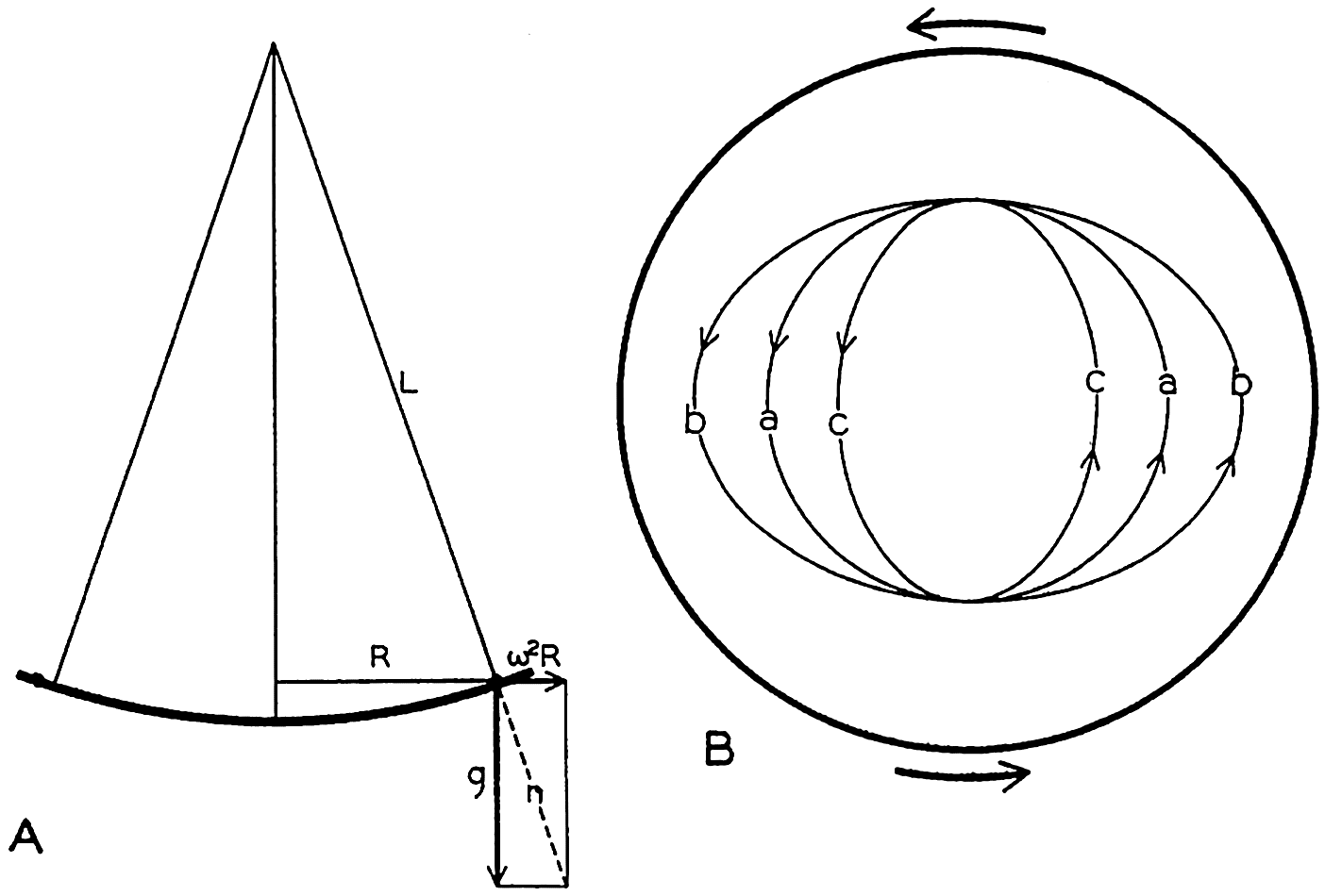
Motion of a body on a rotating disk. (A) Profile of the disk. (B) Different orbits of moving bodies.
[Full Size]
Consider a disk that in an “absolute” system rotates at an angular velocity ω. Assume that a uniform gravitational force acts in the direction of the axis of rotation and that the disk has such a shape that the surface is normal to the resultant of the acceleration of gravity and the centrifugal force (fig. 101). Assume, furthermore, that the surface of the disk is absolutely smooth and offers no frictional resistance to any moving body. On these assumptions a body that rotates with the disk will complete one revolution in the time T = 2π/ω. A body that does not move in respect to an outside observer will, on the other hand, when placed on the disk, oscillate back and forth between two extreme distances from the center, R. The rotation of the disk does not affect this motion, since it has been assumed that the surface of the disk is frictionless. The period of the oscillation is easily found because in the first approximation the oscillation can be considered a pendulum motion (fig. 101). The period of oscillation of a pendulum is
Therefore, T′ = 2π/ω = T, where T is the time in which the disk completes one revolution.
If the observer gives the body a velocity equal to the velocity of the disk at the point at which he places it, the body will travel around with the disk and complete one revolution in the time T = 2π/ω. If the body is given a velocity greater or less than the velocity of the disk (fig. 101b or c), it will describe an ellipse in the same time T.
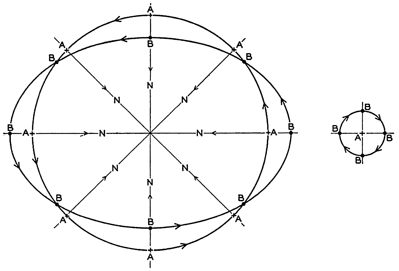
Motion of a body on a rotating disk as seen by an observer who looks down on the disk (left) or by an observer on the disk (right).
[Full Size]
So far, the motion has been described relative to a fixed coordinate system. Now consider what an observer on the disk sees. This observer will refer the motion of the body to a coordinate system which, like himself, rotates with the disk and will, for instance, let the positive x axis point toward the center of the disk (fig. 102). Let the direction of the positive x axis be called north. Assume that the body at the time t = 0 was to the north of the observer and traveling faster than the disk. At the time t = T/8 the body will be to the east of the observer, at the time t = T/4 it will be to the south of the observer, at the time t = 3T/8 it will be to the west, and at the time t = T/2 it will again be to the north. To the observer it will therefore appear that the body travels in circles
The apparent angular velocity of the body will be 2ω, and the linear velocity will be 2ωr, where r is the radius of the circle. In order to account for this motion the observer will say that a deflecting force directed toward the center of the circle exists which exactly balances the centrifugal force of the circular motion. The deflecting force must be equal to
and must in this case be directed at right angles and to the right of the velocity. It has to be considered in all cases, regardless of whether or not other forces are acting.The deflecting force performs no work, because it is always directed at right angles to the velocity. This conclusion is obvious, since the deflecting force is not a physical force but enters in the equations of motion only because the simple equations (XIII, 1) containing the physical forces have been transformed from the fixed coordinate system in which they are valid to a rotating coordinate system. It is a force, however, which, when dealing with relative motion, is just as necessary as any other force for a correct description of the motion, and which to an observer in the rotating system has the same “reality” as other forces.
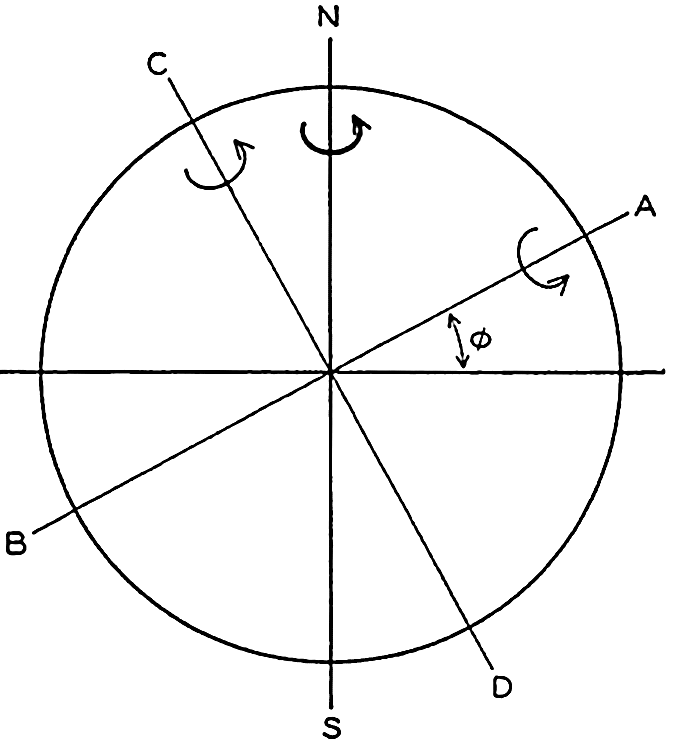
Rotation of the earth around the axis N-S decomposed in rotations around the axes A-B and C-D.
[Full Size]
The above reasoning is directly applicable to conditions very near the poles of the earth, because a level surface on the earth is normal to the resultant of the force of gravitational attraction and the centrifugal force due to the earth's rotation.
In order to find what happens at a locality M at an angular distance of ϕ from the Equator (fig. 103), the rotation around the axis N-S can be considered as resulting from two rotations around the axes A-B and C-D. The angular velocities of rotation around these axes are ω sin ϕ and ω cos ϕ, respectively, if ω is the angular velocity of rotation around N-S. The rotation around C-D produces the vertical deflecting force
If no other forces are acting, the deflecting force must be balanced by a centrifugal force which, if the radius of the orbit is called r, is equal to ν2/r. Therefore
The radius of the orbit remains practically constant if the motion is such that variations in latitude are small, meaning that the particle will move in a circle of radius r. This circle is called the circle of inertia, because this circle, which appears in the relative motion, corresponds approximately to the straight-line inertia movement that characterizes “absolute” motion. In lat. 40° the radius of the circle of inertia is 106 m, 1060 m, and 10.6 km, respectively, if the velocity of the particle is 1 cm/sec, 10 cm/sec, or 100 cm/sec. The angular velocity of the body is 2ω sin ϕ, and the time required for one completion of the circle of inertia is therefore T′ = 2π/2ω sin ϕ. This time is called one half pendulum day, because it equals half the time required for a complete turning of the plane in which a pendulum swings (Foucault's experiment).
The motion in the circle of inertia in the Northern Hemisphere is clockwise, but in the Southern Hemisphere it is counterclockwise. In view of the fact that to an observer who faces the Equator the sun appears in the Northern Hemisphere to travel clockwise across the sky, and in the Southern Hemisphere counterclockwise, Ekman has introduced the term cum sole for describing the direction of motion in the inertia circle in both hemispheres. Similarly, the term contra solem describes rotation in the opposite direction.
It was stated that, when dealing with relative motion, the deflecting force is just as “real” as any other force. It can nevertheless be neglected when dealing with most problems of mechanics because, as a rule, it is very small compared to other forces. For instance, consider an automobile weighing 1500 kg which travels on a flat road in 40°N at constant speed of 75 km/hour (47 miles/hour) when the motor develops 15 kw (20.4 hp). The force per unit mass acting in the direction in which the car travels is then equal to 41.3 dynes/g. As the motion is steady, this force must be balanced by the resultant of the friction against the road and the deflecting force, but the deflecting force per unit mass, f = 2ω sin ϕ ν = 0.02 dyne/g, is less than 1/1000 of the other forces and can be neglected. The physical forces that maintain the motion of the atmosphere and the ocean, on the other hand, are of the same order of magnitude as the deflecting force, which therefore becomes of equal importance.
The effect of the rotation of the earth has been given so much consideration because in most problems the effect of the rotation enters and because the nature of the deflecting force should be thoroughly understood.
Motion in the Circle of Inertia. If the deflecting force of the earth's rotation is the only acting force, the equations of motion are reduced to
which, as already stated, describe motion in the inertia circle. Motion of this type has been observed in the sea. The most striking example is found in a report by Gustafson and Kullenberg (1936), in which are described the results of 162 hours' continuous record of currents in the Baltic. The measurements were undertaken between the coast of Sweden and the island of Gotland in a locality where the depth to the bottom was a little over 100 m. On August 17, 1933, when the measurements began, a well-defined stratification of the water was found. From the surface to a depth of about 24 m the water had a nearly constant density, but between 24 and 30 m the density increased rapidly with depth. Below 30 m a slow increase continued toward the bottom. The current meter, a Pettersson photographic recording meter, was suspended at a depth of 14 m below the surface and thus would record the motion of the upper, homogeneous water.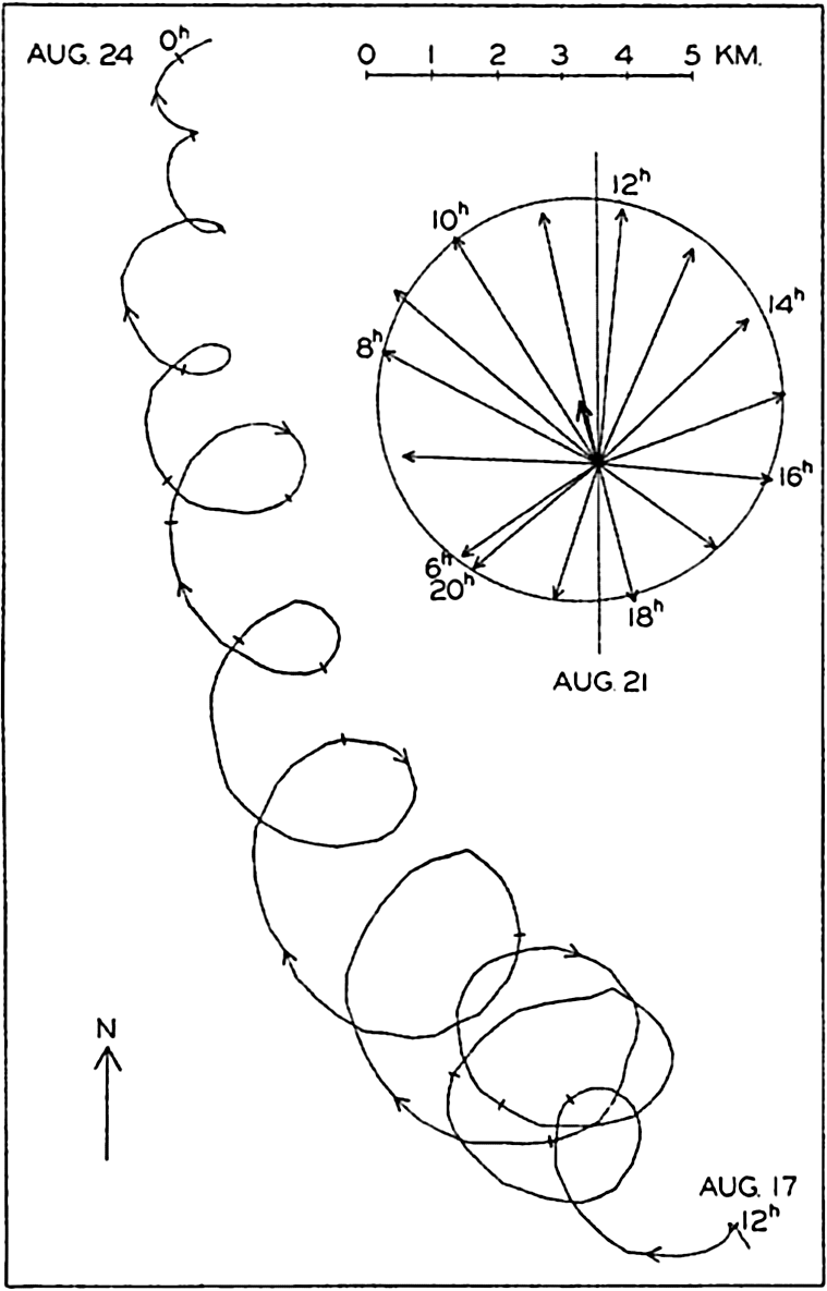
Rotating currents of period one-half pendulum day observed in the Baltic and represented by a progressive vector diagram for the period, Aug. 17 to Aug. 24, 1933, and by a central vector diagram between 6h and 20h on Aug. 21 (according to Gustafson and Kullenberg).
[Full Size]
Gustafson and Kullenberg have represented the results of the records in the form of a “progressive vector diagram” (fig. 104), which is prepared
The curve shows a general motion toward the northwest and later toward the north, and superimposed upon this is a turning motion to the right, the amplitude of which first increases and later decreases. This rotation to the right (cum sole) is brought out by means of the inset central vector diagram in which the observed currents between 6h and 20h, August 21, are represented. The end points of the vectors fall nearly on a circle, as should be expected if the rotation is a phenomenon of inertia, but the center of the circle is displaced to the north-northwest, owing to the character of the mean motion.
The period of one rotation was fourteen hours, which corresponds closely to one half pendulum day, the length of which in the latitude of observation is 14h08m, and on an average the periodic motion was very nearly in a circle. It is possible that this superimposed motion can be ascribed to the effect of wind squalls and that the gradual reduction of the radius of the circle of inertia is due either to frictional influence or to a spreading of the original disturbance, but a theoretical examination by Defant suggests that inertia oscillations of this nature are associated with internal waves (p. 596). This was the case at the Altair station in lat. 44°33′N to the north of the Azores, where a rotating current of period 17h was present (Defant, 1940) corresponding very closely to a period of one half pendulum day and varying with depth in the manner found in internal waves. Ekman (1939) believes that the twenty-four-hour oscillations observed by himself and Helland-Hansen (1931) in about latitude 30°N are related to inertia movement.
The measurements that have been mentioned and other observations of currents made in deep water from anchored vessels (Defant, 1932, Lek, 1938) also show oscillating currents of tidal periods, some of which appear to be ordinary tidal currents, whereas others are associated with internal waves of tidal periods. In most instances, only tidal periods dominate and, according to Seiwell (1942), a period of one half pendulum day is not found in numerous oscillations which he has examined. It should perhaps be concluded that, although inertia movements may be found in the sea, it is still doubtful whether such a type of motion is very common. Arguments can be advanced against the general occurrence of movements in the inertia circle (Ekman, 1939).
The Equations of Motion Applied to the Ocean. When applying the equations of motion to the ocean, certain simplifications can be made. The vertical acceleration and the frictional term Rz can always be neglected. Similarly, the term depending upon the vertical component
At perfect hydrostatic equilibrium the isobaric surfaces coincide with level surfaces, but this is no longer the case if motion exists. At any given time an isobaric surface is defined by (p. 155)
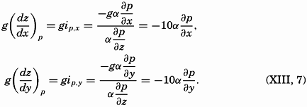
From equations (XIII, 4) and (XIII, 5) one obtains the equation for isobaric surfaces in a moving system: From equations (XIII, 4) and (XIII, 5) it also follows that the components of the horizontal pressure gradient are identical with the components of gravity acting along the isobaric surfaces: The inclination is positive in the direction in which the surface slopes downward.Introducing the geopotential slope defined by iD,x = dD/dx, iD,y = dD/dy, and measuring the geopotential in dynamic meters, dD = gdz/10 (p. 403), one obtains
Thus, the geopotential slope in dynamic meters per meter equals the product of the specific volume and the pressure gradient in decibars per meter. These relations will find extensive use.
A dynamic boundary condition must be added to the kinematic boundary condition (p. 424)—namely, that at any boundary surface the pressure must be the same on both sides of the surface. This condition also applies to internal boundaries, separating water of different density, in which case the condition states only that the pressure must vary continuously. The densities and velocities may, however, vary abruptly when passing from one side of the boundary surface to the other. Calling the densities on both sides ρ and ρ′, and the velocities ν and ν′, and omitting the frictional terms and the accelerations, one obtains the dynamic boundary condition in the form
because along the boundary surface p = p′, where p represents the pressure exerted against the boundary surface from one side and p′ the pressure exerted from the other side. Equation (XIII, 9) must be fulfilled everywhere along the boundary surface and defines therefore the shape of that surface in the same manner that (XIII, 6) defines the isobaric surfaces.The dynamic energy equation is obtained by considering that the work done by a force is equal to the product of the force and the distance traveled in the direction of the force. Multiplying the equations of horizontal motion by νx and νy, respectively, and adding, one obtains
because and because the terms containing the deflecting force cancel. On the left side of the equation stands the increase of kinetic energy per unit volume. On the right side stands the sum of the activity (power) per unit volume of the forces due to pressure distribution and friction.The equation is of small interest because it tells only that the increase of kinetic energy per unit volume equals the work performed per unit volume by the acting forces, but combined with the thermodynamic energy equation it becomes of importance. The complete derivation is given by V. Bjerknes and collaborators (1933), and here only the result for a system which is enclosed by solid boundaries is stated:
Here, W is the amount of heat added to the system, T is the total kinetic energy of the system, Φ is the potential, and E is the internal energy. If the total energy of the system remains unaltered, the amount of heat added in unit time must equal the work per unit time of the frictional forces. If, on the other hand, no heat is added, the work of the frictional forces must lead to a change of the total energy of the system.


