Chapter 5—
Silicic Domes:
Heat Flow around Small, Evolved Magma Bodies
Silicic domes are distinct volcanic structures associated with nearly all types of volcanic landforms; they are perhaps the most common surface expression of evolved magma bodies. Domes and dome complexes are generally found in both early and late stages of silicic caldera evolution. These domes and dome complexes, sometimes the only volcanic feature found in a volcanic field, characterize late stages of composite cone evolution and often form along major tectonic lineaments.
Distinct hydrothermal systems develop below and within silicic domes. The heat source provided by dome lavas is usually short-lived and of little hydrothermal significance, but persistent hydrothermal systems manifested in and around domes are a good indicator of a much larger thermal source at depth below the field. Such thermal sources are commonly moderate-sized, differentiated magma bodies. These hydrothermal systems generally develop in pyroclastic strata and fractured country rocks below the dome that were formed during the initial stages of dome eruption. The systems manifest themselves as fumarolic areas and exhibit extensive hydrothermal alteration in and around the dome. Ishikawa (1970) noted that most geothermal areas in Japan are located in Quaternary volcanic zones, where andesitic and dacitic domes or spines plug crater vents, and in Tertiary volcanic districts that are closely related to intrusions of viscous, acidic magmas.
The following discussions review volcanological characteristics and models of domes as well as their lavas and tephras, the
geothermal systems below that are manifested by these domes, and the relationships among the tectonic setting, magma composition, country rock, and the hydrothermal system. Case histories are drawn from geothermal studies at Coso volcanic field of California, the Usu area of Japan, and the Terre Blanche-Belfond dome complex in the Qualibou caldera of St. Lucia.
Silicic Domes and Extrusion of Viscous Lava
Extrusions of viscous lava form domes in many different volcanic settings during the evolutionary stages of volcanic fields. Because viscosity depends on thermal, compositional, and textural factors, lava compositions from andesite to rhyolite can display relatively high viscosities (105 to 1012 Pa/s; Murase and McBirney, 1973); therefore, the rheology of such viscous fluids is the dominant feature in controlling extrusion mechanisms.
Common Geologic Settings
Table 5.1 lists some common occurrences of domes in various volcanic settings. The most common are lava domes of dacite and rhyolite that form before and after caldera collapse. These extrusions, which generally appear in groups of at least several vents along major structural features such as ring faults and resurgent cores in calderas, are manifestations of larger bodies of differentiated magma at depth. Silicic domes are frequently associated with composite cones in late evolutionary stages (see the discussion in Chapter 7). In these cases, domes form either plugs in the central vent region of the cone or parasitic vents around the flanks of a composite cone. Silicic domes may also occur as isolated extrusions along major tectonic lineaments such as grabens near plate boundaries and rifts. In addition, domes appear in or near explosion craters that are created by gaseous bursts preceding the extrusion of viscous lava.
Evolution and Internal Structure
Figure 5.1 illustrates a common evolutionary scheme for silicic domes. Preceding activity is usually marked by the passive or explosive release of gases at depth above a rising mass of viscous lava. Such a release might be characterized by only fumarolic activity and bulging ground. On the other hand, the gases can be released in violent explosions when high-pressure gases from either vaporized groundwater or the gas-rich top of the magma body burst through the ground surface in crater-producing eruptions. Because of the high viscosity of dome lavas, the extrusion process may continue over periods of months to years. Figure 5.2 depicts types of domes, including both endogenous and exogenous forms. The lava structures formed at domes are distinctive because of the complex rheology as a result of lavas ranging from viscous to
| |||||||||||||||
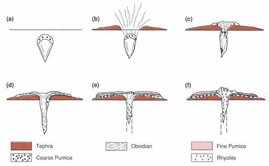
Fig. 5.1
Idealized diagram showing the eruptive evolution of silicic domes. (a) Magma with volatile-rich
pumiceous top approaches surface. (b) Initial pyroclastic eruption in which volatiles and pumice
erupt to form tuff ring. (c) Cessation of explosive eruptions and emplacement of coarsely pumiceous
rhyolite lava. (d) Extrusion of obsidian over coarse pumice. (e) Development of a mantle of finely
pumiceous lava. (f) Final extrusion of crystalline rhyolite.
(Adapted from Fink, 1983.)
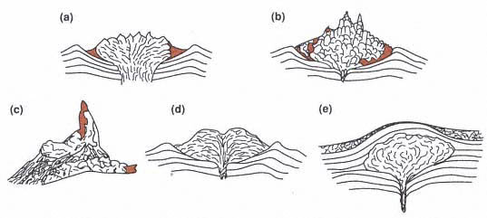
Fig. 5.2
Forms of endogenous and exogenous domes, showing various fracture foliations. (a) Upheaved,
exogenous dome similar to that illustrated in Fig. 5.1. (b) Peléean dome showing vent spines,
blocky fracture, and development of talus aprons. (c) Detail of vent spine of Mont Pelée
(from Lacroix, 1904).
(d) Exogenous dome that discharges viscous flow lobes from a summit vent. (e) Intrusive
dome in which viscous magma body is emplaced just below the earth's
surface and maintains a carapace of upwarped strata.
(Adapted from Williams and McBirney, 1979.)
partly solidified. These lava flows exhibit behavior varying from that of a Bingham fluid to that of a brittle, plastic rock (Shaw, 1972; Hulme, 1974; Fink, 1980a).
The surfaces of silicic lava domes are characterized by a wide variety of textures that produce variations of color, flow layering, crystallinity, and vesicularity. Fractures and foliations in the lava are useful for mapping the surface of domes—and especially for locating the vent area (Fink, 1983; Fink and Pollard, 1983). Figure 5.3 illustrates the development of foliations in lava domes, and Fig. 5.4 shows surface distributions of flow features at an obsidian flow.
Silicic dome lavas generally develop a textural stratigraphy related to their cooling, vesiculation, and crystallization during extrusion (Fig. 5.5; Figs. 5 and 7 in Fink and Manley, 1987). However, such textural features can easily be mistaken for those that develop during the welding of pyroclastic flows. Basal tephra layers are often found because dome extrusions are commonly initiated by pyroclastic eruptions of the gasrich tops of silicic bodies; but a flow breccia, if found above the tephra layer, can distinguish dome/lava-flow stratigraphy from that of welded ash flows. Obsidian layers near the base and top of the flow stratigraphy are similar to the quench vitrophyres that develop in similar positions in welded ash flows. The central portion of dome/lava-flow stratigraphy consists of crystalline lava, which frequently contains lithophysae. This textural type grades upwards into glassy and pumiceous zones that can be mixed into the crystalline part of the flow; in such a complex textural case, it is again difficult to distinguish the lava textures from those of welded pyroclastic deposits. However, scanning electron microscope analysis may differentiate the origin of the complex textural character. For example, vestiges of shard and pumice textures, revealed by electron microscopy, are very flattened and elongated in welded tephra. This distinction is very difficult to observe in rheomorphologically deformed tuffs, and field relationships are used to determine the dome origin of silicic volcanic rocks (Bonnichsen and Kauffman, 1987). Fink and Manley (1987) noted that small domes display little textural variation and usually display structural evidence of their vent geometry. This is not the case for larger silicic lava extrusions because they can exhibit all the textural features discussed above.
Fink and Manley (1987) discuss three principal steps in the development of textures in silicic lava flows and domes.
(1) Crystallization and the accompanying release of magmatic volatiles is strongly related to cooling rate and flow stresses.
(2) Microcracks, formed during the lava's advance, allow gases to escape upward.
(3) Quenching of the upper surface creates a crust of high yield strength that resists flow deformations.
These three processes result in the formation of a gas-rich, low-density layer below the crust that can rise buoyantly. This layer eventually may break through the surface crust, producing the banded appearance of silicic lava flow surfaces. Bonnichsen and Kauffman's (1987) summary for the development of rhyolite lava flow textures is shown in Table 5.2.
Tephra Deposits Associated with Silicic Domes
Pyroclastic activity accompanies most phases of dome growth and is manifested as explosive activity. Newhall and Melson (1987) analyzed explosive activity during volcanic dome growth with respect to history, rate of growth and petrologic controls. Heiken and Wohletz (1987) reviewed dome-related tephra deposits and proposed four main types of eruptions (Fig. 5.6):
(1) Plinian and phreatomagmatic eruptions preceding dome growth,
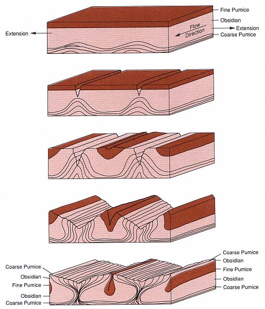
Fig. 5.3
Schematic diagram of lava foliation development. Successive block diagrams show the gradual rise of
coarse pumice diapirs while fractures propagate into the flow along the axes of flow and diapir
anticlines. Fink (1980b) reported that the diapirs form in response to a density inversion between
the relatively dense obsidian overlying the coarse pumice at the base of the flow.
(Adapted from Fink, 1983.)
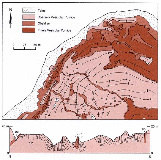
Fig. 5.4
Illustration of the surface geology of a rhyolite flow. This map depicts the northwestern lobe of
the Little Glass Mountain flow in northern California; the cross-sectional profile is from north to
south along the line

and the coarse pumice diapirs are denoted "cp."
(Adapted from Fink, 1983.)
(2) periodic Vulcanian explosions during dome growth,
(3) Peléean and Merapian activity resulting in dome destruction, and
(4) phreatic explosions during hydrothermal and fumarolic activity.
Table 5.3 summarizes the characteristics of tephra produced by these types of eruptions, and they are discussed in more detail here.
Initial Plinian and Phreatomagmatic Eruptions
Magmatic and hydromagmatic eruptions, which commonly herald new extrusions of dome lavas, create tuff rings and cones around vent craters. These eruptions follow depressurization of the gas-rich rising magma and its interaction with ground and surface water.
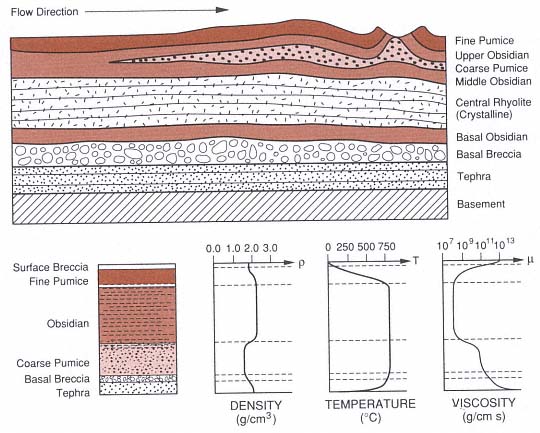
Fig. 5.5
Textural stratigraphy of dome lava. The cross section shows rhyolite lava-flow stratigraphy resulting
from the eruption scenario outlined in Fig. 5.1. The profile of density, based upon actual
measurements, shows an important density inversion at the top of the coarse pumice that
promotes coarse pumice diapirism. The temperature profile is calculated by conductive cooling,
assuming a constant internal temperature, and it shows a steep surface gradient that causes
fracturing. The viscosity profile is based on the laboratory measurements of Friedman et al . (1963).
(Adapted from Fink, 1983, and Fink and Manley, 1987.)
Figure 5.7 schematically illustrates tephra production that precedes dome formation. Magmatic eruptions produce pumice and ash deposits of a Plinian type, whereas phreatomagmatic (hydrovolcanic ) explosions result in fine-ash dispersal during pyroclastic surges and flows, which creates a tuff ring. Such eruptions usually produce most of the tephra associated with domes, but Heiken (1978b) found that their volume generally is relatively small (<0.1 km3 ) to moderate (1.0 km3 ). Near the vent, these tephra are well bedded and capped by lavas from the dome. Where the tephra extend several to tens of kilometers away from the vent, fallout layers are the most common expression.
Vulcanian Eruptive Cycles
Occurring during both growth and destructive phases of dome activity, Vulcanian eruptions tend to be periodic—especially where dome growth is prolonged by new magma
|
rising into previously constructed domes and plugs. Well-documented examples of such activity come from Soufriere of St. Vincent in the West Indies (Shepherd and Sigurdsson, 1982), and the type locality of the Fossa Cone on the Island of Vulcano, Italy (Frazzetta et al ., 1983). Typical tephra deposits consist of ash and lapilli falls, thinly bedded coarse and fine ash, dry and wet surge beds, and lahars. Distinctive of Vulcanian tephra are coarse ash deposits that contain blocky fragments of obsidian, older lavas, and poorly vesicular glass. Pumice fragments tend to be deposited during later stages of the eruptions when new magma reaches the surface and becomes highly vesicular. Most tephra erupted during Vulcanian dome destruction are those typical of hydrovolcanism (Fig. 5.8).
The cyclic activity of Vulcanian tephra production at domes is closely related to both the periodicity of magma rise within the volcano and vent-clearing explosions that provide a pathway for the new magma through older dome lavas. Such cycles are typical of composite cones in late stages of evolution (see Fig. 2.16) when sequences of wet, and then dry, hydrovolcanism are followed by magmatic pumice eruptions and finally by silicic lava emplacement. In areas of coalescing domes, such as ring fracture areas, the cycle may only occur once, leaving a blanket of tephra over older dome lavas.
| |||||||||||||||||||||||||||||||||||||||||||||
Peléean and Merapian Dome Destruction
Tephra deposits found on the flanks of silicic domes developed from disintegration of the extruded lava either closely following or years after its extrusion (Peléean and Merapian, respectively). Such deposits consist of poorly vesicular lithic pyroclasts that were derived from partly to completely solidified lavas emplaced as block and ash flows. Some examples of these products are provided by the 1902 eruption of Mont Pelée, Martinique (Fisher and Heiken, 1982) and the block and ash flows of the 1930 dome collapse at Merapi, Java (Neumann van Padang, 1931). Figure 5.9 illustrates two types of dome destruction, both of which began with the brittle failure of lava. At Mont Pelée, the recently extruded lava spine was apparently highly charged with gas trapped in vesicles; when the lava crumbled, the vesicles violently discharged gas—and thus drove the comminution of the lava. At Santiaguito dome in Guatemala, the front of a silicic lava flow collapsed and disintegrated into a pyroclastic flow because of trapped gases (Rose et al ., 1976). The mechanical strength of the lava can degrade, which produces explosions; this situation is often connected to fumarolic activity. Hydrothermally altered lithic fragments are common in tephra of Peléean and Merapian activity.
Phreatic Eruptions
Phreatic explosions usually produce craters in the vent and fumarolic areas of silicic domes and lava flows. They also produce mantling layers of fine-grained tephra, explosion breccias, and small tuff rings and cones. Although phreatic tephra do not generally contain juvenile components, it is understood that phreatic activity can be a precursor to magmatic eruptions, as is shown in Fig. 5.10. The tephra most frequently associated with favorable geothermal prospects in domes are accidental lithic fragments that are strongly
Fig. 5.6
Stratigraphic relations of dome tephra. Four principal occurrences are schematically illustrated:
(a) Plinian and phreatomagmatic eruptions of tuff rings and cones (shown with overflowing lava
plug), (b) coalescing domes with phreatic and phreatomagmatic carapaces, (c) Plinian, far-field
pumice falls and flows, and (d) Peléean avalanches and Vulcanian intercalated tephra (flank
deposits) at polygenetic domes and composite cones.
(Adapted from Heiken and Wohletz, 1987.)
Fig. 5.7
Schematic illustration of initial Plinian
and phreatomagmatic eruptions
(a) in an initial Plinian stage and
(b) followed by phreatomagmatic explosions.
(Adapted from Heiken and Wohletz, 1987.)
altered and coated with clays. In many cases, phreatic tephra deposits are limited to areas where strong hydrothermal activity has led to a build-up of high-pressure steam below or within a sealed caprock. Failure of the caprock results in steam explosions and the formation of phreatic pits and ejecta layers.
Hydrothermal systems associated with silicic domes take on configurations that are controlled by dome stratigraphy and structure as well as the structural setting of the region. Even though the heat contained in dome lavas may be relatively insignificant, that provided by an underlying differentiated intrusion can drive hydrothermal convection if sufficient water is present. Because water is a fundamental component of eruptions of silicic domes, in this chapter we will reiterate its function and expression in eruption phenomena and then illustrate its subsequent hydrothermal behavior through hypothetical models.
Hydrothermal Systems Associated with Domes
Role of Water in Dome Eruptions
In the above descriptions of dome-related tephra, water from either meteoric or magmatic sources is the primary volatile phase that leads to pyroclast formation. Magmatic water is widely recognized as a primary phase that contributes to the formation of pumice and promotes Plinian tephra emissions. The same water has a profound effect on the development of dome lava textures such as flow foliation, crystallization, vesiculation, and fumarolic (vapor-phase) alteration. The latter effect is especially important in weakening the dome and making it vulnerable to future phreatic or Merapian bursts that produce tephra. On the other hand, meteoric waters also contribute to fumarolic and phreatic activity, and it may be difficult to distinguish its effects from those of magmatic water.
Because water is of such consequence in hydrothermal systems, it is important to identify any evidence of its presence in the dome. The best evidence is hydrovolcanic activity, which is common in the pyroclastic activity that precedes dome extrusion. However, meteoric water is also vital for Vulcanian activity during dome growth. The presence of lahars on dome flanks is most reliable in identifying the presence of meteoric water, whether from rainfall or from saturated conditions of fractured, porous lavas beneath the dome. In the case of either magmatic or hydrovolcanic explosive activity, tephra layers provide avenues for water circulation in hydrothermal systems that are driven by residual magma heat below the dome.
Heiken and Wohletz (1987) discussed the migration of magmatic and meteoric water in dome magma systems as a diffusion process and emphasized that this process can proceed at many different rates, often
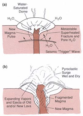
Fig. 5.8
Schematic illustration of Vulcanian tephra
associated with dome destruction in
(a) preeruptive and (b) eruptive stages.
(Adapted from Heiken and Wohletz, 1987.)
well above those established by laboratory measurements (Shaw, 1972). High effective diffusion rates are expected for hydrovolcanic situations in which meteoric water diffuses from host rocks into the rising magma to cause magma/water interactions such as explosive phenomena and the pervasive chemical alteration of tephra. The development of lithophysae and vaporphase alteration and crystallization, which are generally attributed to magmatic water diffusion in extruded lava, can proceed at rates higher than those expected for slow molecular diffusion because of fracture flow of vapors produced by degassing and devitrification of glass to nonhydrous phases. We mention these processes to emphasize the importance of recognition of the presence of water in silicic dome systems.

Fig. 5.9
Schematic illustration of Peléean and Merapian
dome destruction. (a) An initial failure of the
dome leads to a landslide followed by
decompression of trapped vapors, which
produces a rapidly moving pyroclastic avalanche
and surge. (b) This scenario, described by
Fisher and Heiken (1982), can be promoted by
intrusion of volatile-rich magma, which may vent
after dome failure (c). (d) Destruction of lava
flow fronts that are weakened by fumarolic
activity also produces block and ash flows,
as proposed by Rose et al . (1976).
(Adapted from Heiken and Wohletz, 1987.)
Geothermal System Models
The following discussion of geothermal systems associated with domes presents some possible models for hydrothermal circulation that reflect conditions observed in the field, some of which have contributed to exploitable geothermal systems. These models include systems associated with
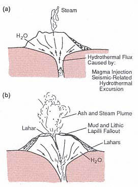
Fig. 5.10
Schematic illustration of phreatic tephra
associated with silicic domes. (a) A passive
fumarolic stage might be enhanced by a rapid
change in hydrothermal flux so that (b) vigorous
vapor emission opens a vent and discharges
lithic ash and lahars (Heiken et al ., 1980)
(Adapted from Heiken and Wohletz, 1987.)
· tephra aprons surrounding domes,
· cratered domes,
· faulted domes,
· dome complexes,
· caldera ring fault domes, and
· caldera resurgent extrusive domes.
The models highlight the importance of pyroclastic materials in locating hydrothermal systems. Each of these dome types may be modeled by the heat flow program discussed in Chapter 2.
A review of pyroclastic rock physical properties indicates that pumiceous materials range in bulk density from 200 to 1200 kg/m3 , and
bedded ash—often less vesicular because of its hydrovolcanic origin—may range from 1000 to 1500 kg/m3 . If a particle density of 2300 kg/m3 is assumed, pumice has a void space between 50 and 90%; bedded ash varies from 35 to 60% void space. The primary permeability of pyroclastic rocks is provided by both vesicles and intergranular spaces. Whitham and Sparks (1986) showed that at temperatures >150°C, the pumice vesicles are effectively interconnected and readily allow absorption and movement of water. However, the primary permeability of pyroclastic materials can rapidly decay during hydrothermal circulation because circulation promotes the solution of glass and the redeposition of silica and secondary minerals that effectively seal the tephra.
Tephra Aprons
Figure 5.11 depicts a hypothetical dome extruded over a tephra collar that resulted from initial explosive eruptions. The collar extends down into the vent area and defines the crater and tuff ring apron onto which lava was extruded. Porous tephra allows hydrothermal fluids to rise convectively. The heat source is a magma conduit below the dome; water in the country rock below the dome promotes heat convection upward into the tephra. In this situation, fumarolic activity at the base of the dome demonstrates the existence of the hydrothermal system, which is locally capped by dome lavas. The dome lavas have a lower permeability and do not permit much heat transfer.
Cratered Domes
Figure 5.12 depicts a second hypothetical case: a dome with a crater formed by either Vulcanian or phreatic activity that was driven by intrusion of magma below the dome. Below the crater, a region of strongly fractured lava and breccia provides a pathway for the convective rise of hydrothermal fluids from the cooling magma at depth. Here again, the water supply is from country
Fig. 5.11
Schematic illustration of geothermal system in
which a vapor-dominated zone is concentrated
in the porous tephra apron. This very
hypothetical system is based on heat
transported convectively from a magma
chamber at depth below the dome upwards
along the vent conduit.
rock into which the magma has intruded. In such a situation, the dome will have a mantle of Vulcanian or phreatic tephra that provides evidence of the explosive origin of the crater. By examining the isotopic and chemical nature of fumarolic gases and rock alteration in the crater, it is possible to determine the origin of the vapors, whether solely magmatic (and hence limited) or meteoric and of potential economic significance.
Faulted Domes
Figure 5.13 presents a dome cut by a fault that has triggered collapse of the dome— perhaps in a Merapian fashion. The fault has fractured lavas and basement rock sufficiently to allow strong convection of hydrothermal fluids into the dome. The fumarolic alteration of fault breccias and related pyroclastic breccias is evidence of the convective heat source. In this case, the tectonic activity has altered heat flow from depth and, where residual magmatic heat exists below the dome, the faulting provides a new circulation pathway.
Dome Complexes
Where numerous dome extrusions have occurred in a volcanic field (for example, along the ring fault system of a caldera or within a graben), lavas and dome-related tephra layers overlap. The lavas act as caprocks and the pyroclastic layers serve as geothermal reservoirs. Figure 5.14 illustrates such a situation in which heat from the youngest eruptive activity drives hydrothermal circulation below: steam reservoirs exist at some depth below the dome and in older tephra layers. In areas consisting of many overlapping dome extrusions, high conductive heat flow at the surface may indicate a convective system at depth.
Caldera Domes
Two cases of caldera-related dome extrusions are depicted in Fig. 5.15. In one case, domes along the ring faults manifest magma intrusions at depth that control the
Fig. 5.12
A cratered dome may have a prolonged
fumarolic stage during which a convective
system develops within the crater conduit in
response to a new magma body
intruded at depth.
overall heat flow toward the margins of the caldera. In the other case, resurgence of the caldera creates a structural or extrusive dome that may produce hydrothermal convection towards the center of the caldera. In the first instance, recharge of the hydrothermal system is strongly controlled by the hydrology of the down-thrown region of the caldera, which acts as a ground-water concentrator or trap. In the instance of the resurgent caldera, the hydrothermal system is recharged from higher topographic regions surrounding the caldera. Both of these models are simplified, but they demonstrate the way convective heat flow in calderas can develop in diverse manners. There is no simple rule-of-thumb that is adequate for determining where to explore in a caldera. The existence and locations of young silicic domes are helpful in predicting recharge and outflow areas of possible hydrothermal systems.
Fig. 5.13
Tectonic activity at a relatively young dome
produces fracture pathways along newly
activated faults; this activity allows deep
circulation of meteoric water downwards to a
still-hot magma body at depth. Such a faulted
dome may develop vigorous fumarolic activity
as a surface manifestation of a subsurface
hydrothermal system, but gradual sealing of
the fractures by alteration minerals and silica
will eventually slow the fluid convection.
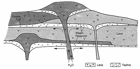
Fig. 5.14
Dome complexes form when lavas overlap their related pyroclastic sheets. The stratigraphy of a dome
field is characterized by various potential hydrothermal reservoirs in porous and formation-permeable
pyroclastic strata that are capped by one or more impervious lavas. Most recent dome eruptions
result from renewed thermal infusion from related magma bodies at depth. Vapor-dominated reservoirs
characterize upper pyroclastic horizons, whereas deeper ones may be brine-filled.
Fig. 5.15
Caldera domes form both (a) along ring fracture zones of calderas and (b) within the resurgent cores.
The character of caldera-fill materials and their formation permeability works in conjunction with
caldera faults to allow deep circulation of meteoric water. The magma conduits below such zones
probably occur directly above the caldera magma chamber, where it is closest to the surface.
Because silicic caldera magma bodies are relatively large, hydrothermal systems developing below
related dome structures may have prolonged activity and high heat flux.
Structural Influences
In addition to the localized stratigraphic and volcanic structure that influences the development of geothermal systems associated with domes, regional structure and tectonics can also strongly affect these hydrothermal systems. Six structural settings for domes and their effect on the development of hydrothermal circulation are (1) caldera faults; (2) extensional block faulting; (3) tectonic plate convergence; (4) basin fill; (5) intrusive deformation, sector grabens, and radial faults around volcanoes; and (6) volcanic fracture systems. These features, four of which we briefly discuss here, are of more regional significance than the models discussed above.
Caldera Faults
Figure 5.16 shows the pattern created by the intersection of regional linear faults with the ring faults of a caldera. In this example drawn from the Qualibou caldera on the island of St. Lucia in the West Indies (Wohletz et al ., 1986), the youngest domes are expressions of caldera resurgence. The regional and still active fault system controls the location of fumarolic activity
Fig. 5.16
Structural control of domes associated with
calderas is generally related to regional fault
trends and caldera ring fractures. Because
regional faults may remain active long after
caldera tectonics have declined, the most
recent dome activity will be found
along such faults.
near the young extrusions. Young faults are important because they maintain a fracture permeability in rocks that otherwise are sealed by secondary minerals and silica. Where regional faults intersect caldera ring faults, greater fracture permeability can also be expected. Although the presence of young dome lavas and pyroclastic materials is useful for determining a potential geothermal area, it is the structural elements that are the most significant when actually locating a hydrothermal system.
Block Faulting and Grabens
Strongly developed block faults can localize extrusive features such as domes. Figure 5.17 depicts a hypothetical dome that is emplaced along the margins of a graben deeply filled with several kilometers of sediments. The hydrology of the graben is influenced by both the topographically high recharge areas in surrounding horst blocks and the deep, permeable graben fill. Such a situation promotes not only deep circulation of meteoric waters but also the development of extensive hydrothermal convection along margins of the intrusive body below the dome. In such cases, it is difficult to characterize the geothermal potential as either volcanic or tectonic. Block faulting in extensional areas may result in a thinner crust and greater heat flow so that deep circulation of meteoric water alone can develop a geothermal system. However, the same tectonic regime is typical of volcanic systems that develop in rifts.
Intrusive Deformation
Silicic domes indicate the existence of intrusive bodies at depth. Figure 5.18 illustrates a situation in which a laccolith is associated with a dome in a compressed tectonic region. The laccolithic intrusion has domed and created concentric and radial faults in the country rocks above it. An intrusion such as a laccolith or a buried
dike can produce small phreatic craters (Miller, 1985; Fink, 1985) of structural features of localized extensional surface deformation (Mastin and Pollard, 1990).
Henry and Price (1990) described laccolithic doming associated with caldera formation in the Christmas Mountains of Trans-Pecos, Texas. Most of the magmatism in this area is expressed as small (1- to 4-km-diameter) laccolithic intrusions that commonly involve high-silica, peralkaline rhyolites and quartz trachyte. These intrusions have formed structural domes of steeply tilted sedimentary strata. Field relations show that these domes were emplaced along ring fractures during the evolution of larger caldera structures. Numerous sills occurring around the flanks of the laccolithic domes are cut by radial faults that probably formed in response to the deformation associated with dome intrusion.
Basin Fill
A basin filled with lahars shed from a dome on the basin margin is shown in Fig. 5.19. Lahars can be impervious to fluid flow because of the cementation mechanisms promoted by ash carried in lahars. In the model shown, the lahars have capped pyroclastic materials erupted earlier from the dome. Hydrothermal circulation below the dome is confined within the pyroclastic strata, and hot water flows from the dome into the basin below the laharic apron. In such cases, lahars mask the geothermal system at depth and geophysical or geochemical methods are needed to confirm the existence of the system in the basin.
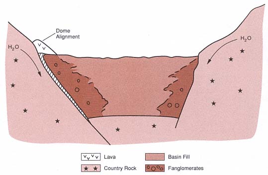
Fig. 5.17
The block faults that bound basins in extensional terranes frequently have long histories and deep
extensions. This structure may be accompanied by sufficient crustal heat flow to cause crustal
melting (for example, by basalt intrusion) and silicic dome emplacement. Deep circulation of meteoric
water from the horst highlands through the graben-filling sediments can promote hydrothermal
activity within graben-bounding fault breccias and along intrusions (hachured) below domes
(v pattern) that were extruded along these faults.
Fig. 5.18
Intrusive deformation associated with domes is
manifested by uparching and fracturing of rocks
above a laccolith. Hydrothermal circulation
can then develop around and above
the laccolith as it cools.
Coso California Geothermal Field
The Coso volcanic field is in eastern California on the western edge of the basin and range province of the western United States. About 35 km3 of volcanic rocks have erupted and overlie principally Mesozoic plutons associated with the Sierra Nevada batholith; The Coso volcanics range in age from ~4 to 0.04 Ma and vary in composition from basalt to rhyolite. Pleistocene rhyolitic domes are the major volcanic features, and these are cut by numerous normal faults that may reflect late Cenozoic extension. Along some of these faults within the dome field, fumaroles and hot springs provide evidence of a high geothermal gradient. Recent geothermal development by the California Energy Company, Inc., resulted in nearly 90 wells. The first production well, drilled to a depth near 2000 m, had a bottomhole temperature of ~340°C and produced dry steam. At this time, with drilling operations still under way, nine power plants have been completed and are online with a net capacity of 230 MWe. The Coso volcanic field exploration is considered one of the best documented investigations of a silicic dome system in the world. We summarize here the work of Bacon and Duffield (1980) at Coso as an example of a geothermal system developed in Mesozoic basement rocks below silicic domes.
Geologic Setting
The Coso range is a horst block immediately east of the Sierra Nevada range in eastern California. It is covered by a veneer of ~400 km2 of mostly lava flows and domes of late Cenozoic age. Early geologic exploration (Ross and Yates, 1943; Dupuy, 1948) identified mercury, which has been mined in fumarolically altered rocks near rhyolite domes; numerous subsequent studies have described pyroclastic and volcaniclastic deposits, the general stratigraphy, potassium-argon ages, and geothermal phenomena. Duffield et al . (1980) documented both the relationship of the volcanic rocks to an underlying granitic basement (Fig. 5.20), which is exposed within the volcanic field and along its margins, and the nature of a late Cenozoic extension, which is marked by north-northeast-trending normal faults that have produced considerable uplift of horst block under the range.
The geothermal system has developed in a Mesozoic basement of dominantly granitic plutons and subordinate mafic plutons and metamorphic rocks associated with the Sierra Nevada composite batholith. Late Tertiary and Quaternary volcanic rocks drape over the basement. Duffield et al . (1980) used potassium-argon and obsidian-rind techniques to determine that ~35 km3 were erupted between 4.0 and 0.04 Ma (Fig. 5.21). These volcanic rocks include 38 separate domes and flows of phenocryst-poor, high-silica rhyolite, most of which are likely younger than 0.3 Ma.
The oldest lavas, alkalic basalt flows, are the most voluminous and widespread of Pliocene volcanic rocks (Fig. 5.22) and were erupted from cinder cones onto a relatively subdued terrain. They occur as notable stepfaulted flows in the eastern portion of the field. These lavas are overlain by Pliocene andesite, dacite, rhyodacite, and rhyolite flows and tuff. Andesite and dacite occur as parts of polygenetic volcanoes in which dacite flows, shallow intrusive masses, and pumice are interlayered with andesite flows and
Fig. 5.19
Basin-filling clastic rocks shed from a growing
silicic dome can provide a permeable formation
for a hydrothermal reservoir—especially when
continued down-warping of the basin allows
it to be filled with impervious sediments such
as lahars. These lahars efficiently hide the
geothermal reservoir, which develops at
some distance from the volcano.
cinders. Rhyodacite is found in widespread pumice fall and lava flows, and Pliocene rhyolite forms a nonwelded pumiceous ash flow that is intercalated with sedimentary volcaniclastic rocks of the Coso Formation.
The youngest volcanic rocks are Pleistocene in age and consist of contemporaneous alkalic basalt and high-silica rhyolite (Bacon et al ., 1980). Most basalt vents are marked by partly eroded cinder cones that fed one or more lava flows on the east, south, and west sides of the rhyolite field. Pleistocene rhyolites compose the 38 steep-sided domes as well as some short, thick flows whose surfaces are notably perlitic and pumiceous. Bacon et al . (1981; 1984) inferred that the rhyolite magma (total extruded volume @ 1.6 km3 ) erupted from a chemically stratified magma chamber, which formed when mantle-derived basalts partially melted crustal rocks. Most domes have extrusive volumes of <0.3 km3 and are located within and/or above tephra rings that were formed by the initial explosive phases of dome eruption. The tephra from these dome eruptions have a total volume of ~0.3 km3 and consist of well-bedded obsidian, pumice, and rhyolite clasts and minor amounts of lithic fragments from basement rocks. Accretionary lapilli and impact sags provide evidence that the tephra are in part hydrovolcanic. Tuff rings average about 600 m in diameter, and rim deposits range from several meters to 30 m thick. Most of the rhyolite field is mantled by tephra similar in character to those in the tuff rings. The first production well completed by California Energy is collared within the tuff ring of dome 53 near the Devil's Kitchen fumarolic area (Fig. 5.23). Intensely fractured Mesozoic basement rock encountered by the well can be attributed to several processes, including hydraulic fracturing associated with hydrovolcanic explosions that occurred during the initial eruptions of this dome, thermal stresses exerted by elevated heat flow, and ongoing tectonic movement. Other geothermal wells are being bored in the area around dome 53.
Using the distribution of silicic vents, the volume of extruded magma, gravity and seismic surveys, and heat flow measurements, Bacon et al . (1980) predicted that a silicic magma body ~5 km in diameter and >1 km thick (a total volume of at least 20 to 30 km3 ) underlies the Coso volcanic field at a depth of at least 8 km. It is possible that the silicic magma body may still be partially molten, if one applies the reasoning that the most recent basaltic eruption occurred as late as a few thousand years ago and that such extrusions are evidence that heat was supplied to the magma body from an underlying mafic reservoir. Bacon (1982) indicated that the ages of extrusive rocks (Friedman, 1976), plotted in Fig. 5.21 with respect to cumulative volumes, show a trend that suggests these eruptions will continue in the future.
Figure 5.24 illustrates three sets of faults in the Coso Range (Duffield and Bacon, 1979; Roquemore, 1980) that indicate principally late Cenozoic crustal extension; outward dips of the Coso Formation demonstrate considerable uplift of the range during Pliocene time. A west-northwest-trending set of apparently vertical faults are well developed in the southern and western parts of the range. This fault set is an expression of
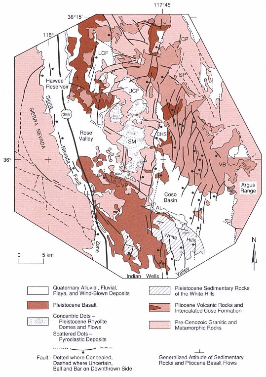
Fig. 5.20
Geologic map of the Coso volcanic field of California, showing distribution of major rock units and
faults. Abbreviated locations: CP = Coso Peak, LCF = Lower Cactus Flat, UCF = Upper Cactus Flat,
SP = Silver Peak, CHS = Coso Hot Springs, SM = Sugarloaf Mountain, VB = Volcano Butte,
VP = Volcano Peak, AL = Airport Lake, and LL = Little Lake.
(Adapted from Duffield et al ., 1980.)
Fig. 5.21
Rock volumes and compositions vs radiometric age for the Coso volcanic field. Volumes were
calculated by using the geological map area and cross-sectional exposures and allowing for
material removed by erosion. Volumes of pyroclastic rocks were converted to dense rock
equivalence by multiplying by 0.5. Exponential thickness decreases with distance were
applied to pyroclastic deposits. In the last 4 Ma, ~35 km3 of lava has been erupted, of
which 31 km3 erupted before 2.5 Ma ago.
(Adapted from Duffield et al ., 1980.)
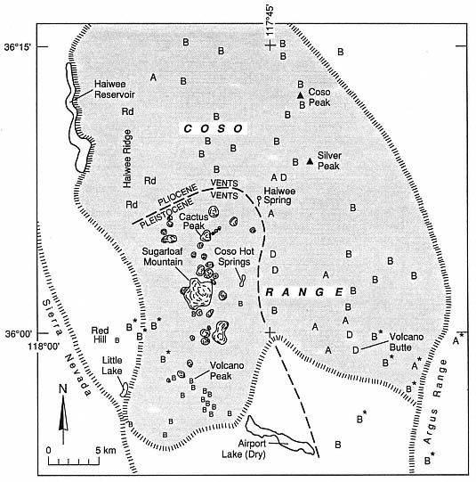
Fig. 5.22
Distribution of eruptive vents in the Coso volcanic field of California. The locations of vents are
shown by letters designating the composition of materials erupted: B = basalt, A = andesite,
D = dacite, and Rd = rhyodacite. Asterisks denote the location of
Late Pliocene and early Pleistocene vents.
(Adapted from Duffield et al ., 1980.)
regional structure and, although these faults do not offset Pleistocene rhyolite, some of the silicic domes are aligned along their strike. The basin and range morphology of the Coso range is developed along north-to northeast-trending normal faults. These faults cut the horst onto which the rhyolites have been erupted and form en echelon sets that are consistent with north-northwest right lateral shear. In Fig. 5.25, information from Bacon et al . (1980) shows that the Quaternary maximum horizontal compression follows this northeast trend. This interpretation arose from consideration of the distribution of domes and application of the stress analysis suggested by Nakamura (1977). Arcuate faults present in the northern and northeastern parts of the field are approximately
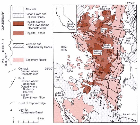
Fig. 5.23
Generalized geological map of the principal geothermal area in the Coso geothermal area. Coso Hot
Springs emanate along major graben-bounding faults, whereas geothermal drilling has focused on
the region around Sugarloaf Mountain rhyolite dome and the Devil's Kitchen fumarolic area. Hulen
(personal communication) reports that drilling in regions around these
vents has encountered intensely fractured basement rock.
(Adapted from Bacon et al ., 1980.)
concentric around the geographic center of the field and dip inward toward this center. This set of faults was originally interpreted as part of a caldera structure (Austin et al ., 1971; Koenig et al ., 1972), and more recently, Roquemore (1980) has attributed their origin to strike-slip movement; however, Duffield (personal communication, 1990) is not convinced by either of these interpretations. The step-faulted terrane in the eastern part of the volcanic field near Airport Lake (see Fig. 5.23) is attributed to downwarping and down-faulting in response to late Cenozoic crustal extension that caused an effective decoupling of that terrane from a block-faulted terrane to the west and south. Figure 5.26 depicts the step-faulted terrane that forms a graben structure and its relationship to the horst on its west side onto which the rhyolite domes have been extruded. An ongoing study by California Energy indicates that new interpretations of structural relationships will be required to fully understand Coso's geothermal system.
Hydrogeochemistry
Most present-day surface thermal activity is concentrated within and immediately east of the Pleistocene rhyolite field, apparently along an east-northeast-trending zone between Sugarloaf Mountain and Coso Hot Springs—a zone mapped as a fault by Hulen (1978). Coso Hot Springs consists of fumaroles and intermittently active, acid-sulfate springs and mud lakes that emanate from a north-northeast-trending fault along the east side of the main horst block. Surface flow is related to local precipitation, but water samples from a 125-m-deep well are alkaline and chloride rich (~3,000 ppm of chloride); the bottomhole temperature was 142°C (Austin and Pringle, 1970). South of this area are laminated siliceous sinter and travertine exposures that are evidence of older, widespread thermal springs. Fumaroles of Devil's Kitchen, occurring in the tuff ring of dome 53, are noted for their present-day deposition of sulfates, sulfur, and cinnabar. Although these surface expressions are not chloriderich and are typical of a high-level, vapordominated system, the chloride-rich waters from wells in this immediate vicinity indicate that at depth there is a hot-water-dominated hydrothermal reservoir (White et al ., 1971).
Fig. 5.24
Detailed structural map of the Coso Range and adjacent area, showing distribution of faults.
Location abbreviations are those used in Fig. 5.20; shaded patterns denote rhyolite domes.
(Adapted from Roquemore, 1980.)
The hydrothermal system at Coso is apparently controlled by fractures in the Mesozoic granitic and older metamorphic basement rocks. Water samples from two wells of this system were analyzed by Fournier et al . (1980), and their chemistry is summarized in Table 5.4. Although the chemical analyses show variability that can be attributed to evaporative concentration, water/rock reactions at different temperatures, and different sample preservation and laboratory procedures, the samples exhibit essentially the same chloride content, and water of relatively uniform composition is found throughout the permeable rock underlying the Coso area sampled. The chloride content also indicates a hot-water-dominated rather than a vapor-dominated system.
Geophysical Character
Numerous geophysical techniques have been applied to the geothermal exploration of the Coso area: heat flow measurements, microseismicity and teleseismicity, gravity, magnetics, and electrical resistivity. Taken together, these methods have provided mutually supportive data that promote the development of a subsurface model to locate and define the nature of the magma
Fig. 5.25
Idealized axis of maximum horizontal tectonic compression of the Coso area is determined from
(a) the orientation of normal faults, location of rhyolite domes, and sense of strike-slip displacement
(inset) in zones of seismic epicenters (Walter and Weaver, 1980). This relationship is compared to
(b) the idealized horizontal cross section of a large volcano (Nakamura, 1977), which shows
the effect of a differential horizontal stress on dike propagation (curves) from a region of magma
storage and ascent (shaded) underlying the Sugarloaf Mountain area. Dikes fed the outlying domes
around the Sugarloaf Mountain area (shown by heavier lines).
(Adapted from Bacon et al ., 1980.)
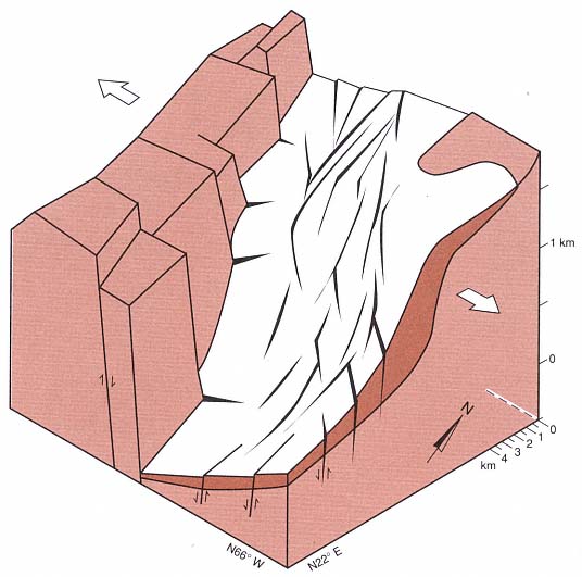
Fig. 5.26
Generalized block diagram illustrating the step-faulted terrane (dark lines and wedges) and block
faulting in the Coso Basin near Airport Lake (see Fig. 5.20). Pleistocene rhyolite domes have
erupted on the horst; the step faulting has developed in response to Cenozoic crustal extension
(arrows). The cenozoic basement is shown by light stipple and Pliocene volcanic rocks are dark
stippled. Coso Hot Springs emanate along the northeastern extension of the western graben-
bounding fault, and geothermal drilling is mostly on the crystalline horst
(Adapted from Duffield et al ., 1980.)
heat source as well as determine the structural and lithological control of heat flow.
Combs (1980) reported the results of thermal gradients measured in 25 shallow-depth and 1 intermediate-depth boreholes in addition to thermal conductivity measurements on 312 core and cutting samples from the igneous and metamorphic basement rocks. Figure 5.27 shows equilibrated thermal gradients for shallow boreholes where temperatures ranged from 25.3 to 906°C/km. The high gradients are a product of thermal convection by hot water, and the low gradi-
| ||||||||||||||||||||||||||||||||||||||||||||||||||||||||||||||||||||||||||||||||||||||||||||||||||||||||||||||||||||||||||||||||||||
ents are caused by conduction of heat away from dikes that fed domes and lava flows. Figure 5.28 shows isotherms at 5- and 10-m depths. These data correspond to terrain-corrected heat flows that range from 1.6 to 23 heat-flow units (HFU; 1 HFU = 41.84 mW/m2 ). Background measurements for the region are between 1.6 and 2.4 HFU. Heat-flow contours enclose the area being developed for geothermal energy near dome 53 and Devil's Kitchen (Fig. 5.29). Heat flows near 4 HFU divide the convective regimes of high heat flow from conductive regimes; the 3- and 5-HFU contours in Fig. 5.29 generally parallel regional structure, which suggests that convective heat flow is controlled by the circulation of hot water along fault and fracture systems in the rhyolite dome fields.
As is shown by Fig. 5.30, microearthquakes are common in the Coso Range (Walter and Weaver, 1980); a magnitude 1.0 or greater earthquake occurs almost every day in the region. Zones of seismicity strike radially outward from the rhyolite field, and earthquake swarms show a general northwest trend across the field. Fault-plane solutions show a regional north-south compression. Earthquake depth varies little across the field: most quakes are around 5 to 6 km deep. This trend suggests that the brittle-to-ductile transition does not rise under the field as would be the case if near-liquidus temperatures occurred at a shallow level. However, Young and Ward (1980) did find a shallow zone of high teleseismic P-wave attenuation within the upper 5 km in a region under Coso Hot Springs, Devil's
Kitchen, and Sugarloaf Mountain—probably corresponding to vapor and liquid in near-surface lithologies. Furthermore, Reasenberg et al . (1980) found significant teleseismic-wave delays that were likely caused by a low-velocity body of partially molten rock concentrated from 8 to 17.5 km directly below the region of highest heat flow.
Although gravity data from Plouff and Isherwood (1980) reveal the regional tectonic patterns, they do not predict a mass deficit for a magma reservoir underlying the Coso Range. A magnetic-low area that corresponds to the area of high heat flow near Coso Hot Springs can be explained by a poorly magnetized silicic pluton that crops out inthe area; much of its magnetite may have been destroyed by hydrothermal fluids. Jackson and O'Donnell (1980) reported telluric current and 7.5-Hz audio-magnetotelluric data that reveal major resistivity lows associated with conductive basinfill materials (such as those underlying the region directly east of Coso Hot Springs) and a secondary low trough that extends across the geothermal area (Fig. 5.31).
Volcanological Interpretations
Although none of the data sets is conclusive in itself, taken together, the geological, hydrogeochemical, and geophysical evidence pinpoints the area now being developed as a geothermal resource. However, most of the geophysical conclusions—and
Fig. 5.27
Idealized equilibrium thermal gradient profiles for 24 shallow boreholes at the Coso geothermal area.
Profile numbers refer to boreholes shown in Fig. 5.28. In general, boreholes with high thermal gradients
are located in the immediate vicinity of the Devil's Kitchen and
Sugarloaf Mountain thermal manifestations.
(Adapted from Combs, 1980.)
some of the geochemical ones—are based upon geological field observations. As Duffield et al . (1980) showed in a schematic east-west cross section of the Coso Range (Fig. 5.32), the concentration of young, rhyolitic volcanism on a horst block, the prevalence of phreatic and phreatomagmatic tephra in tuff rings below the silicic domes, and through-going regional faults all point to a region that should be characterized by high heat flow, convective water circulation, and fractured rock. Such is the case for the Coso geothermal field.
Usu Volcano, Japan
Most geothermal fields in Japan are developed around young volcanoes or intrusives. Very few of these fields are associated with basaltic volcanoes. As was mentioned earlier, Ishikawa (1970) states that geothermal areas commonly develop around lava domes of viscous, silicic compositions and that these extrusions plug a crater vent and then prevent gases and heat from freely escaping into the atmosphere. Figure 5.33 indicates the locations of volcanoes on Hokkaido island; Usu volcano is in the southwestern part of the island. The Toya hot springs are of particular geothermal interest because their development at the foot of Usu volcano was well documented during the emergence of the Meiji-Shinzan cryptodome in 1910.
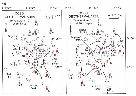
Fig. 5.28
Temperatures at depths of (a) 5 m and (b) 10 m for shallow heat flow boreholes in the Coso geothermal
area. The colored numbers and symbols refer to boreholes referenced in Fig. 5.27, and the numbers
below the symbols are measured temperatures (°C). Note that isotherms shown by solid lines are
concentric to the Sugarloaf Mountain and Devil's Kitchen thermal areas.
(Adapted from Combs, 1980.)
Fig. 5.29
Heat flow contour map for depths <65 m in boreholes and generalized geology of the Coso
geothermal area (taken from Duffield et al., 1980). Borehole heat flow values are shown beside each
borehole (

to Duffield et al. (1980). Fumarole areas are stippled; heavy solid lines are faults (bar with ball on
downthrown side); and hachures outline areas of internal drainage (Moyle, 1977).
(Adapted from Combs, 1980.)
Fig. 5.30
Number of earthquakes vs depth for Coso volcanic field. The · and

geothermal-related earthquakes in the geothermal area shown in Fig. 5.29.
Most earthquakes are at depths between 5 and 6 km.
(Adapted from Walter and Weaver, 1980.)
Geology
Usu volcano is a truncated composite cone (Katsui et al ., 1981) located on the southern margin of Toya caldera (Fig. 5.34). During historic times, three dacite domes and seven cryptodomes formed on Usu. The 1910 activity included phreatic explosions that produced a zone of 45 craters on the northern foot of the volcano, and a number of hot springs formed along this zone just after the eruptions (Fig. 5.35). The 1910 activity was apparently initiated when magma intruded into a shallow region of abundant groundwater. Subsequent eruptions at Usu from 1943 to 1945 (Showa-Shinzan dome) and from 1977 to 1978 (Usu-Shinzan cryptodome) were well documented. Repeated hydrovolcanic activity during these eruptions resulted in numerous vulcanian explosions as well as new fumarolic areas, and magmatic bursts produced widely dispersed
pumice falls (Fig. 5.36). The 1977 to 1978 activity consisted of two major stages: (1) paroxysmal magmatic pumice eruptions in August 1977 and (2) phreatic and phreatomagmatic bursts beginning in November 1977 and continuing intermittently for nearly a year.
All of the historic eruptions involved calcalkalic rhyolite that, in general, gradually decreased in silica content to dacitic compositions. Katsui et al . (1978) has interpreted this change in composition as evidence of progressive downdraw of a compositionally zoned magma chamber.
Geophysical Properties
Regional gravity studies (Yokoyama, 1964) mainly show the anomaly of the Toya caldera (Fig. 5.37), but seismic observations such as those related to the Showa-Shinzan eruption (Minakami et al ., 1951) revealed shallow hypocenters beneath Usu (Fig. 5.38). Minakami et al . (1951) distinguished three types of volcanic tremors—all of low frequency. "A-type" tremors have a predominant period of ~0.3 s, clear S waves, nearly constant amplitudes at various epicentral distances, and hypocenters deeper than 0.5 km. "B-type" tremors are recorded for shallow hypocenters; they have predominant periods from 0.2 to 0.6 s and unclear S waves. "C-type" tremors, which occur during extrusion of lava, are also called harmonic tremors .
Hydrogeochemistry
The first hot spring produced at Usu after the 1910 activity had a temperature of 42°C, but wells drilled later show higher water temperatures, which increase from near the lake to the explosion crater zone where water temperature is 85°C and the Cl- content is 4.261 g/l (Ishikawa, 1970). Fukutomi (1960) recognized two types of hot springs: Type I, found near Meji-Shinzan, has Cl > SO4 > HCO3 and Type II, at greater distance from the young cryptodome, has SO4 > HCO3 > Cl. The major cationic components of each are very similar; that is, Na >> Ca > Mg. Because the water level in the explosion craters is nearly the same as that of Lake Toya, Nakamura (1962) suggested that the hot-springs water originated from the lake and was heated by the cryptodome Meiji-Shinzan. Definite changes in the temperature and chemistry of hot springs were documented before the most recent activity at Usu, and these changes apparently coincide with the monthly frequency of volcanic earthquakes (Fig. 5.39).
Differences in tephra chemistries noted in the eruptions from 1977 to 1978 are also geochemically significant and useful (Kondo et al ., 1979). Pumices from the first-stage magmatic eruptions are grayish-brown in color (SiO2 = 53.91 to 57.55 wt%), weakly alkaline, and rich in water-soluble Ca2+ and Na+ , but poor in water-soluble Cl- and

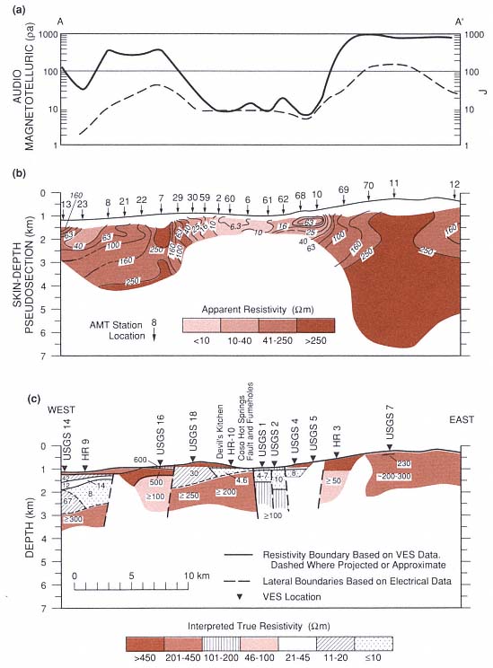
Fig. 5.31
East-west electrical cross sections from Rose Valley across Devil's Kitchen, Coso Hot Springs,
and Coso Basin (see Fig. 5.20). (a) Audiomagnetotelluric (AMT) at 7.5 MHz (heavy line) and Telluric J
(dashed line). (b) Pseudosection skin depths and apparent resistivities from AMT soundings, whose
locations are shown by numbered arrows. (c) Interpreted depths and true resistivities from
Schlumberger vertical electrical soundings, whose locations are shown as HR (Furgeson, 1973)
and USGS (Jackson and O'Donnell, 1980). A section of conductive alluvial deposits occurs in
Rose Valley (west side) and Coso Basin. A secondary resistivity low, occurring in the geothermal
area between Devil's Kitchen and Coso Hot Springs, is caused by a shallow conductive zone that is
interpreted as hydrothermally altered basement rocks containing saline geothermal water.
(Adapted from Jackson and O'Donnell, 1980.)
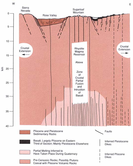
Fig. 5.32
Schematic east-west cross section of the Coso Range through Sugarloaf Mountain. The horizontal
scale is equal to the vertical scale, and there is some surface topography exaggeration. This section
summarizes the geological and geophysical interpretations for the origin of high heat flow from a
rhyolite magma chamber under a horst of crystalline basement rocks on which rhyolite domes have
been extruded. This interpretation emphasizes the fact that the geothermal heat emanates not from
the young domes themselves, but from the postulated underlying magma chamber.
(Adapted from Duffield et al ., 1980.)
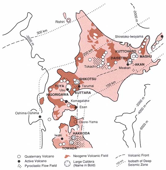
Fig. 5.33
Volcanoes of Hokkaido, showing the Toya caldera and Usu volcano in the southcentral
portion of the island just west of the volcanic front.
(Adapted from Katsui et al ., 1981.)
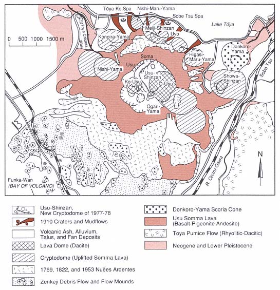
Fig. 5.34
Geologic map of Usu, located on the southern margin of the Toya caldera, which is occupied by Lake
Toya. Usu is a collapsed composite volcano with a small summit caldera that is filled by several dacitic
domes and flanked by the Showa-Shinzan dome and cryptodome. The dome eruptions of Ko-Usu,
O-Usu, and Showa-Shinzan, as well as 7 other cryptodomes of Usu, occurred in historic times.
(Adapted from Katsui et al ., 1981.)
Fig. 5.35
Map of phreatic explosion craters formed during the 1910 activity at the base of Usu volcano.
The Toya hot springs, formed in 1962, became major geothermal direct-use features. This map was
drawn before the eruption of Showa-Shinzan volcano just south of Nishi-Kohan.
(Adapted from Ishikawa, 1970.)
Terre Blanche-Belfond in St. Lucia
The dacitic domes of Terre Blanche and Belfond grew in response to resurgent volcanic activity that occurred in the middle of the Qualibou Caldera on the island of St. Lucia, 20,000 to 40,000 years ago (Tomblin, 1964; Wohletz et al ., 1986). The geothermal potential of Sulphur Springs at the base of Terre Blanche was recognized early by Bodvarsson (1951) and Robson and Willmore (1955). An initial exploration project at Sulphur Springs began with seven wells that were drilled to depths up to 726 m (Merz and McLellan, 1976). Temperatures in these wells exceeded 200°C, and steam and geothermal brine were encountered in four of the wells. This exploration project was terminated because of a lack of fracture permeability in some wells, high CO2 content in the steam, and economic difficulties. Recent drilling performed for the St. Lucia government by a consortium of supporters has added two deep wells, one of which is located at the base of Terre Blanche dome and has a projected capacity of ~8 MWe.
Geology
Volcanism has occurred over the last 8 Ma in southern St. Lucia. In the area of the Qualibou caldera, 5- to 6-Ma-old basaltic lava flows are overlain by 0.75- to 1.0-Ma-old andesitic and dacitic composite cones, upon which lie caldera-related rocks: andesitic to dacitic tephra falls and pyroclastic flows of ~0.04 Ma as well as intracaldera dacitic lava domes and tephras of ~0.02 to 0.32 Ma (Fig. 5.40). Figure 5.41 is a map of the caldera showing the locations of geothermal wells between the dacitic domes of Terre
Blanche to the north and Belfond to the south. Sulphur Springs, the main area of geothermal manifestation, consists of boiling acid springs and fumaroles. The springs extend along a zone of strongly altered rocks that are located on the trace of northwest-southeast-trending regional fault between its intersections; there is an arcuate caldera-collapse fault along Rabot Ridge on the west and an approximately north-south fault splay that cuts the western side of Terre Blanche.
Figure 5.42 shows a cross section along line B—B' of Fig. 5.41. This section illustrates the substructure of the caldera and the caldera infilling of lavas and tuffs associated with Terre Blanche and Belfond. The most recent, well-dated volcanism (20,900 to 34,000 yrs; Wright et al ., 1984) caused the partial phreatomagmatic destruction and cratering of the Belfond dome; it also produced a southerly directed pyroclastic surge and flow deposit that formed a tuff-ring deposit over the southern margin of the dome (Wohletz et al ., 1986). Because fallout from this eruption does not drape Terre Blanche (although the fallout dispersal axis trends north-northeast and is up to 30 m thick in the caldera), it appears that the extrusion of Terre Blanche may postdate Belfond. The numerous phreatic explosion craters between Terre Blanche and Belfond apparently are aligned along caldera and regional faults. Detailed mapping of faults in
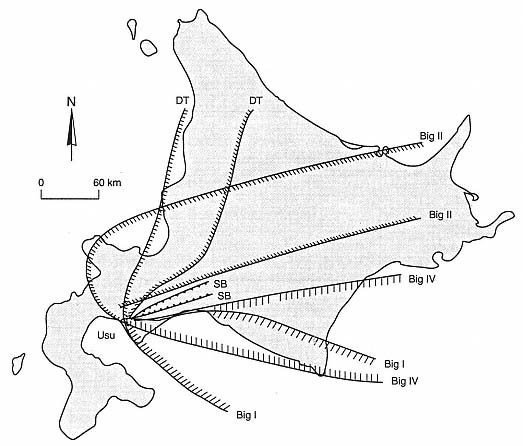
Fig. 5.36
Map of the distribution of tephra from Usu Volcano during the August 1977 eruptions indicates
the extent of measured ash falls from several major episodes of
activity called the Big I, Big II, Big IV, DT, and SB.
(Adapted from Katsui et al ., 1978.)
Fig. 5.37
Regional Bouguer gravity near Usu, showing the anomaly associated with the Toya caldera. Gravity
contours and measured gravities are given in milligals.
(Adapted from Yokoyama, 1964.)
Fig. 5.38
Distribution of seismic hypocenters of A-type
(circled dots) and C-type (small dots) earthquakes
in plan view and along cross sections A-A'
and B-B'. Minakami et al . (1951) related the
clusters of shallow C-type hypocenters just
under the summit of Usu (at the intersection of
the cross sections) and on its eastern flank
to magma movement in a
conduit below growing domes.
(Adapted from Minakami et al ., 1951.)
the caldera is limited by the thick cover of pyroclastic debris from these late stage eruptions. Steam found in well 7 (see Fig. 5.41) was encountered at depths and in lithology that coincide with those of the tuff ring under Terre Blanche, which is exposed on its northeastern side. The steam field underlying Sulphur Springs is thought to have developed in the fractured lavas and breccias of precaldera andesites.
Geophysical Properties
Electrical surveys of the Qualibou caldera have been successful in identifying major faults and general structural features at depth that were predicted by geological cross sections. Greenwood and Lee (1976) completed dipole-dipole resistivity profiles with penetration to 700 m that indicated surface anomalies of conductive rock along linear features corresponding to faults. Ander (1984) extended these data to nearly 2.5 km below Sulphur Springs. Apparent resistivities plotted as a pseudosection in Fig. 5.43 show a resistivity high that corresponds to dacite lavas below the Belfond dome and resistivity lows that are thought to represent conductive geothermal brines along the northern and southern caldera rim faults as well as a deep brine reservoir beneath Sulphur Springs. The higher resistivity zone at an intermediate depth below Sulphur Springs corresponds to depths where wells intersected steam-producing strata; this anomaly is likely produced by dry steam, which is poorly conductive. Gandino et al . (1985) also present gravity data that apparently delineate a positive gravity anomaly in the caldera structure—the result of a relatively dense caldera fill; their audio-magnetotelluric data indicate deep electrical discontinuities related to major faults.
Hydrogeochemistry
Geochemical studies of this area have been performed by Bath (1976; 1977), Aquater (1982), and Goff and Vuataz (1984). Consideration of new data and previous studies led
Fig. 5.39
Plot of seismic frequency, hot-spring temperature, and bicarbonate content for the
period 1975 through 1977 at Usu volcano. These three indicators rose
sharply in months preceding the 1977 eruptions.
(Adapted from Katsui et al ., 1981.)
Goff and Vuataz to conclude that a geothermal reservoir underling the Sulphur Springs area consists of an upper-steam condensate zone, an intermediate depth, two-phase zone, and a lower brine zone. Sulphur Springs display chemical compositions (Table 5.5) very characteristic of acid-sulfate systems in which mixtures of steam and other gases condense in the near-surface environment and oxidation of H2 S and H2 SO4 leads to acidic conditions. The springs have relatively low pH, high SO4 , and a low Cl content; divalent and trivalent cations (Ca, Mg, Al, and Fe) dominate Na + K, and most trace elements other than B are relatively scarce. Bath's (1977) brine analyses of well 4 (see Fig. 5.41) show considerable variability because of wet and dry cycling of the flow from the well, which indicates variable steam loss from the brines sampled. Goff and Vuataz (1984) noted that this brine is extremely unusual because the Ca content is twice that of Na by weight and it is very rich in B.
Although drilling encountered temperatures >220°C at depths of 700 m (Williamson, 1979), oxygen isotope composition, gas geothermometry, steam enthalpy, and B abundances indicate brine reservoir temperatures are near 280°C. Figure 5.44 (Goff and Vuataz, 1984) shows a model of the geothermal system beneath the Sulphur Springs area in which geothermal upflow could occur beneath Sulphur Springs and possibly below Belfond—the areas of most recent silicic dome eruptions. Lateral outflow occurs near the surface in the condensation zone, but there is also a strong possibility that it occurs below the vapor zone, where deep brines flow northward and pool against the north caldera-wall
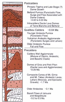
Fig. 5.40
Generalized stratigraphy of Qualibou caldera near
the Terre Blanche dacite dome on St. Lucia. The
stratigraphic section represents a thickness of
~2 km and reflects a general trend from
precaldera mafic andesites and basalts through
intermediate products of caldera-related
eruptions to postcaldera eruptions associated
with silicic dome rock. A vapor-dominated
hydrothermal system is thought to exist in
pumice sections just below the intracaldera
dome lavas, and there is probably a brine
reservoir in the fractured caldera-
fill and precaldera rocks below.
faults. The brine composition indicates it originated from sea water that reacted with basaltic rocks in the subsurface and was subsequently replaced by meteoric water.
Volcanological Interpretations
Young volcanism that filled the Qualibou caldera took the form of dacitic lava out-pourings, which built the Terre Blanche and Belfond domes. This volcanism indicates a magmatic heat source of sufficient size and youth to retain magmatic temperatures at depths of several kilometers or more. Extensive evidence of phreatomagmatic eruptions that postdate the domes is recorded by numerous explosion craters and tephra blankets. Because fragments of the deep basaltic strata exist in the phreatomagmatic tephra and the geochemistry of the brine points to seawater/basalt chemical interactions, it appears possible that a geothermal reservoir formed after dacitic magma intruded into the lower part of the volcanic stratigraphy below the Qualibou caldera (Fig. 5.45). Intersections of caldera ring faults and through-going regional faults have provided fracture permeability along which deep brines have risen. The steam reservoir may exist in still porous and permeable tephra layers and in the caldera fill and precaldera breccias.
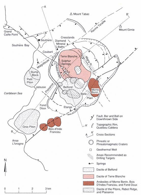
Fig. 5.41
Geologic map of the Qualibou caldera on St. Lucia, showing the major silicic dome complexes of Terre
Blanche and Belfond that were erupted after caldera collapse. Exploratory geothermal drilling (Wells 1
through 7) has concentrated on a regional northwest-southeast-trending fault zone that runs between
these two domes. Note the alignment of two large phreatic craters along this fault zone and those along
the ring fracture that extends through the Belfond dome. The depth to precaldera basaltic rocks in
well 2 is at least several hundred meters less than in nearby well 1, which suggests the location of
a western caldera ring fault that exposes precaldera Piton-type dacites.
(Adapted from Wohletz et al ., 1986.)
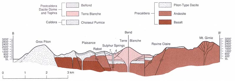
Fig. 5.42
Cross sections along B—B' (see Fig. 5.41) under Terre Blanche dome. Stratifications illustrated at the base of the Terre Blanche
dome denote the pumice-rich tuff ring strata that was erupted before the extrusion of dacite lava. Formation permeability in
these tuffs has allowed a vapor-dominated reservoir to develop. This reservoir is connected by fractures to a deeper brine
zone in the Choiseul Pumice and precaldera andesites below. Geothermal wells 7 and 4 (see Fig. 5.41) intersected these units.
(Adapted from Wohletz et al ., 1986.)
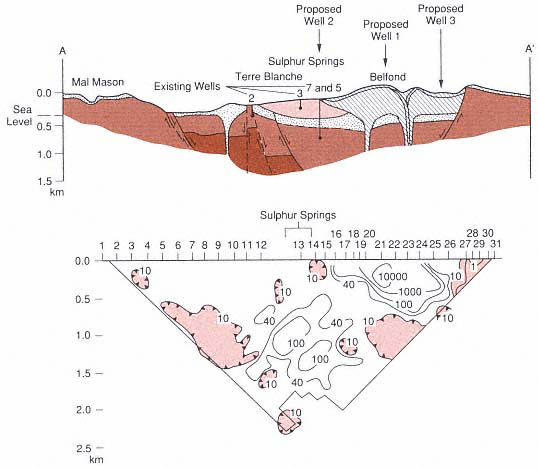
Fig. 5.43
Geophysical resistivity pseudosection along cross section A–A' (see Fig. 5.41) running west of
Terre Blanche and under the Belfond dome. The apparent resistivity high (W-m) under the Belfond
dome represents relatively unfractured dacite lavas, whereas the closed contours of resistivity
lows beneath the north and south caldera margins and below Sulphur Springs are thought to reflect
brine reservoirs. Intermediate resistivity contours below Sulphur Springs at a depth of H1 km probably
indicate the poor conductivity of dry steam. Three exploratory wells were proposed on the basis of
the location of resistivity lows, the geology, and geochemical indicators.
Proposed well 2 produced steam (~300°C) at a depth of ~1400 m.
(Adapted from Wohletz et al ., 1986.)
Fig. 5.44
The hydrogeochemical model of the Terre Blanche-Sulphur Springs area shows a vapor
zone over a brine zone as well as upflow under Sulphur Springs and Belfond. The
condensation of steam and mixing with surface aquifers produce later flow toward
the northern caldera margin, which feeds Diamond Spring.
(Adapted from Wohletz et al ., 1986.)
| ||||||||||||||||||||||||||||||||||||||||||||||||||||||||||||||||||||||||||||||||||||||||||||||||||||||||||||||||||||||||||||||||||||||||||||||||||||||||||||||||||||||||
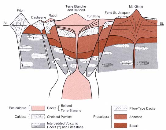
Fig. 5.45
A schematic geological model cross section of the Qualibou caldera from west to east shows (with
some vertical exaggeration) how the dacitic domes have filled in the caldera above the Choiseul
Pumice, which was erupted during caldera collapse. Strong evidence for the caldera structure is
provided by the precaldera basalt that is exposed at the surface near the Piton as well as at many
other locations in southern St. Lucia but is found at depths >1 km in geothermal wells inside
the caldera. The magma chamber is shown as two bodies; the outer one is andesitic and
the source of the precaldera and caldera intermediate rocks, whereas the inner body is
dacitic and represents magmatic resurgence that caused eruption of the dacite domes.
The hypothetical depth of these chambers (~4 km) is drawn from measured geothermal gradients.