Irrigation Systems for Riparian Zone Revegetation[1]
John Disano, Bertin W. Anderson, and Robert D. Ohmart[2]
Abstract.—Revegetation of aridland riparian zones with native riparian species is feasible, but generally requires initial irrigation to maintain the plants while root systems are established. For most desert riparian revegetation work, the irrigation pump should be gasoline- or diesel-powered. Main irrigation lines should be PVC (polyvinyl chloride) buried about 31 cm. (12 in.). Laterals should be polyethylene tubing because this can safely lie on or near the surface. The water should be delivered to each tree through pressure-compensating emitters.
Introduction
We have been reintroducing native riparian species of trees and shrubs on an experimental basis along the lower Colorado River riparian zone since 1977. In this region, irrigation is a necessary prerequisite to any successful revegetation effort. Irrigation is critical in getting vegetation root systems established; it is also a major expense associated with revegetation efforts. In our work we have used two different systems. One was established in 1978 on a barren dredge-spoil area of about 30 ha. (75 ac.); the other was established on a 20-ha. (50-ac.) plot from which salt cedar (Tamarixchinensis ) had been cleared. Both systems delivered water to 2,500 plantings and included about 19 km. (12 mi.) of pipe. In this report, we describe and evaluate the major systems with which we have had experience. Advantages and disadvantages of each system are noted and recommendations are made for designing irrigation systems for revegetation. English units of measurement are used in order to be consistent with units currently in use in the irrigation industry.
Dredge-Spoil System
The irrigation system on the dredge-spoil revegetation site was assembled from polyvinyl chloride (PVC) irrigation pipe. A well was drilled that reached water at 3 m. (10 ft.); water from this well contained approximately 1100–1400 ppm total dissolved solids. A Worthington Model 8M-28 electric pump developing 20 hp at 1760 rpm was installed on the well (fig. 1). Pump bowls were set at 50 ft. The pump had a 5-in. suction pipe and a 6-in. discharge pipe. Water was delivered from the pump through an Olson-Filtomat Model FLT-3000 vacuum cleaning filter with a capacity of 250 gpm (fig. 1). This filter is an automatic backwash filter with a hydraulic controller which detects pressure differential between the intake and outlet valves of the filter. From the filter, water entered a pressure-regulating valve (fig. 1) which was set to maintain 35 psi in the irrigation system. Before entering the main line, water passed two pressure-sensitive electrical cutoff switches (fig. 1). One switch was set at a high pressure of 40 psi, the other was set at a low pressure of 30 psi. Any time the pump was running and the irrigation system control panel was set on automatic, an increase or decrease in pressure to the above settings automatically broke the electrical
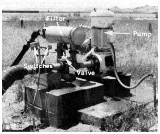
Figure 1.
Dredge-spoil pump station.
[1] Paper presented at the California Riparian Systems Conference. [University of California, Davis, September 17–19, 1981].
[2] John Disano is Research Biologist, Bertin W. Anderson is Faculty Research Associate, and Robert D. Ohmart is Associate Director; all are with the Center for Environmental Studies, Arizona State University, Tempe, Arizona.
circuit and turned off the pump. These automatic cutoff switches protected the integrity of the irrigation system in the event of a failure of the pressure-regulating valve or a major break within the irrigation system.
The main body of the irrigation system consisted of a 750-ft. long, 6-in. PVC main line running from the pump station to the Colorado River (fig. 2). At the river a butterfly valve was installed along with a bypass pressure relief valve. The entire capacity of pumped water could be discharged into the Colorado River with the butterfly valve open; there was no discharge if the valve was closed. The bypass pressure relief valve was a final safeguard to protect the irrigation system. If all other safeguards failed, the value would open at 50 psi and bleed water into the Colorado River, thereby relieving pressure on the system.
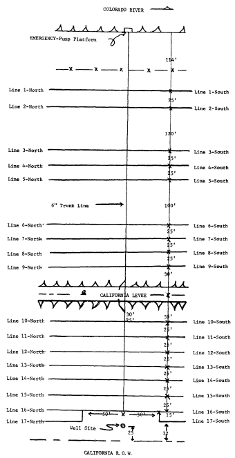
Figure 2.
Map of the irrigation system, dredgespoil site.
Seventeen laterals, each 2,000 ft. long, were installed north of the main line; 17 laterals, each 1,500 ft. long were installed south of the main line. The main line and all lateral lines were buried 15–20 in. Risers for irrigation were placed every 20 ft. along laterals (fig. 3).
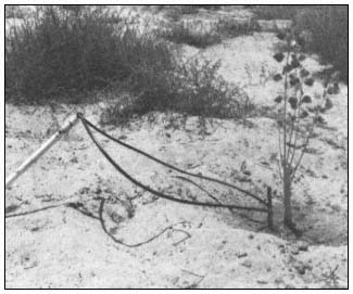
Figure 3.
Riser with Subterrain Dual Flapper emitter and tubing.
The emitters used to deliver water to the trees were Subterrain Dual Flappers. These emitters are pressure-compensating and delivered 4 gal. per hour with a system pressure between 15–50 psi. Tubing was attached at each end of an emitter to deliver a point source of water to the base of a tree (fig. 3).
With the dredge-spoil irrigation system in full operation, the pump delivered 167 gal. per minute at a system pressure of 35 psi. This pressure was chosen because the last emitter along a 2,000-ft. lateral still delivered a pressure of 18–20 psi, while the first emitter near the main line had a pressure of 35 psi. Therefore, both emitters were within the recommended 15–50 psi, and each delivered 4 gal. per hour to its respective tree.
Another pertinent point concerning the irrigation system is that the main line could be opened or closed by a butterfly valve at the well or the river, thus permitting irrigation water to be supplied from the well or from the Colorado River by an auxiliary, trailer-mounted pump. Any one or more laterals could be shut off at the
main line by turning a shutoff valve. Also, any one or more of the 2,500 emitters could be capped temporarily or permanently to prevent further irrigation of trees.
A major disadvantage of this system is that it is expensive to purchase and to install. Purchase and installation costs amounted to $34 per tree.
Refuge Site
The irrigation system on the refuge site received water from the lower Colorado River. This water contained 600–800 ppm total dissolved solids. The water was delivered to the revegetation site by the Cibola National Wildlife Refuge concrete-lined canal (fig. 4). A jack gate was installed (fig. 4) to divert water into two intake ports (fig. 5) of a holding pond (fig. 6). In addition to providing a seven day supply of water for irrigation, the pond also served as a settling basin. This was important because a drip irrigation system using microtubing or emitters with small orifices may be blocked or damaged by dirt or sand.
Water was pumped from the pond using an 8-hp., two-cycle Wisconsin-Robbins engine with a centrifugal pump (fig. 7). This pump delivered 90 gal. per minute at 20 psi to the main line.
A prescreen filter, made from a 3-ft. section of 6-in. PVC pipe with vertical slits and with the open ends covered with fine mesh wire, was fastened to the intake hose and suspended from a barrel float in the pond (fig. 8). The purpose of the prescreen filter was to prevent leaves, sticks, and other debris from being drawn into the pump. A Yardney Model-8 Free Flow manually cleaned filter was installed between the pump and main line (fig. 9). This filter had a capacity of 125 gal. per minute.
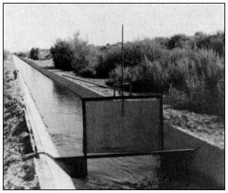
Figure 4.
Cibola National Wildlife Refuge, concrete-
lined irrigation canal and jack gate.
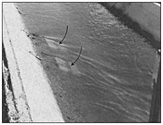
Figure 5.
Intake ports in canal.
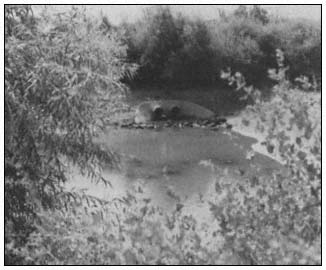
Figure 6.
Holding pond at low-water level to show intake ports.
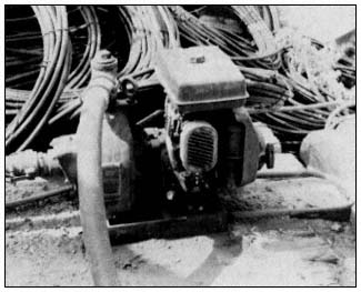
Figure 7.
Engine and pump.
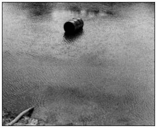
Figure 8.
Barrel float in pond.
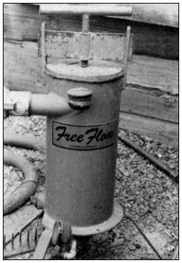
Figure 9.
Free Flow filter.
The irrigation system on the refuge was assembled using regular 3-in. diameter aluminum sprinkler irrigation pipe for the main line transport of water. The laterals were flexible black polyethylene tubing with an inside diameter of 0.58 in. The maximum length of any lateral was 750 ft; none of the pipe was buried.
The site was divided into four 750- x 530- ft. sections (fig. 10). Water to each section was supplied by 17 lateral lines; each lateral supplied 38 trees. The main line of 3-in. diameter aluminum sprinkler pipe was 1,500 ft. long, with the pump located at the center. The north and south submains were both 530 ft. long.
The installation of two 3-in. gate valves (fig. 11) in the main line near the pump permitted the watering of either the north or south section separately or simultaneously. Further flexibility in design was incorporated by installing a ball valve (fig. 12) on each lateral so that any one or more laterals could be shut off during irrigation.
Each lateral valve assembly contained one Subterrain pressure regulator (fig. 12), which prevented main-line water from entering the lateral at more than 20 psi. This was to prevent bursting of laterals and blowing out of microtubes due to a pressure surge; it also assured equal distribution of water to all 68 laterals. The pressure at the beginning of a lateral was 20 psi; pressure at the end was 8–10 psi.
Each tree was watered by two microtubes (fig. 13), each delivering water at a rate of 1 gal. per hour. Any individual tree could be cut off from watering by removing the microtubing and installing "goof" plugs. In order to provide 1 gal. per hour delivery from each microtube, microtube length was varied as shown in figure 10. Appropriate microtube lengths were determined by a computer using the flow characteristics of the system.
Purchase of the system and installation costs associated with this system were much less than that for the dredge-spoil system, amounting to $3 per tree. However, maintenance costs ($16 per tree) were higher than for the dredge-spoil system ($11 per tree).
Evaluation of Irrigation Systems
In comparing the dredge-spoil irrigation system with the refuge irrigation system, there are several factors to consider. One important factor is the availability of electricity. In most areas along the lower Colorado River, electricity is not available. If a system based on electrical pumping is necessary, then revegetation efforts would have to be limited to areas where electricity is available. In most of these areas there is likely tobe competition for land from farming or some form of urbanization. Cost of pumping with electricity is comparable to that for gasoline-powered pumping, but the cost of an electrical pump is about 20 times greater than for a gasoline pump. Locations for a gasoline or diesel-powered pump are limited only by the availability of free-flowing or well water.
A second important consideration is that flowing water is preferable for irrigation if total dissolved solids are low enough to permit plant growth. Water from a well has anaerobic bacteria; the combination of their chemical reactions with those of aerobic bacteria in irriga-
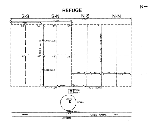
Figure 10.
Refuge site, map of irrigation system. Note: for
0.035 I.D. microtube, use various lengths as shown.
North side of the field is the same as the south side.
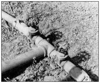
Figure 11.
Gate valves.
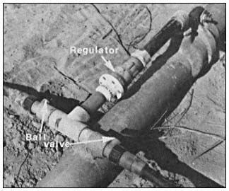
Figure 12.
Lateral valve assembly.
tion systems produces an orange or rust-colored precipitate that must be continuously flushed from lines and/or emitters. This problem usually does not occur when free-flowing river water is used for irrigation.
PVC pipe must be buried because of algae development and deterioration of the pipe when exposed to sunlight. Burying pipe is both labor-
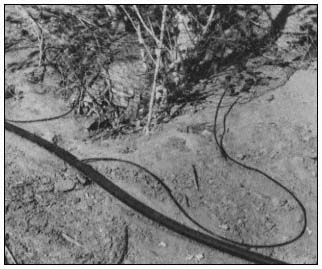
Figure 13.
Microtubing at tree.
intensive and expensive (Anderson and Ohmart 1981[3]) . Black polyethylene tubing accumulates very little algae and can be laid on the surface; in addition, it can be picked up and moved to another area relatively quickly. Also, if polyethylene tubing is damaged it can be repaired easily and cheaply on the surface. PVC pipe is about 10 times more costly than polyethylene tubing.
The decision of whether to use the very inexpensive microtubing or pressure-compensating emitters is more difficult. Although emitters would initially cost six to eight times more than microtubing, they last longer and provide more uniform water distribution over natural, sloping terrain. Also, the cost of labor for installation of emitters is about one-half that of microtubing.
Recommendations
For irrigating most desert riparian revegetation areas, the pump should be gasoline- or diesel-powered and should pump free-flowing water. For flexibility and durability, PVC pipe should be used in main irrigation lines; it must be buried in the soil about 12 in. Lateral lines should be polyethylene tubing with pressure-compensating emitters.
Acknowledgments
We wish to thank Susan M. Cook, Jane R. Durham, Dr. Julie K. Meents, and Cindy D. Zisner for editorial assistance. Marcelett Ector and Cindy D. Zisner typed the numerous drafts of the manuscript. We are grateful to Dr. F. Aljibury, Les Ede, and Jule Meyer, University of California Agricultural Extension Service, Riverside, for their advice and cooperation. James Moore and Judy Huff prepared the figures. Our work was supported by USDI Bureau of Reclamation and the USDI Fish and Wildlife Service Contract No. 7-07-30-V0009.
[3] Anderson, B. W., and R. D. Ohmart. 1981. Chapter 5. In : Revegetation efforts along the lower Colorado River. Final report, in preparation, to USDI Bureau of Reclamation, Boulder City, Nevada.