3—
Magnum Per Parva
The high-tension accelerators stretched the power of insulators and the nerves of physicists to the breaking point. They also taxed the finances and furnishings of the few institutes in which they were developed: they demanded unusual electrical service, special apparatus and safety precautions, and, above all, space, a commodity more precious even than money in the laboratories of the time. An obvious way to relieve the tension on men, material, and money was to accelerate particles in several steps, each requiring only a moderate electrical force. The high-voltage energy would be accumulated on the particles, not on the apparatus.
The idea, we say, was obvious. It occurred to several, probably to many, physicists and electrical engineers during the 1920s. But between theory and its realization stood the usual malevolence of the inanimate and the conservatism of persons who are not inventors. Three examples will illustrate the variety of problems encountered in realizing the principle of acceleration by steps: the proto-betatron, the proto-linac, and the cyclotron.
The Electrical Vortex
The beam of charged particles undergoing acceleration constitutes a current that can be considered the secondary ciruit of a transformer. Recall the watchword of the faith of the electrodynamicist: F = evH / c , where F signifies the force exerted on a particle carrying a charge e and moving with velocity v by a
[39] Allibone in Hendry, Cambridge physics , 154, 165, 172; McKerrud to Cockcroft, 5 June and 14 Jul 1930, and Hopwood to N.R. Davis, 11 Jul 1930 (CKFT, 20/59). For European forerunners of Cockcroft's multiplier, see Ising, Kosmos, 11 (1933), 155–7.
magnetic field of strength H , and c stands for the speed of light.[40] For the formula to hold, H must be perpendicular to the plane defined by v and r . Since F stands at right angles to v , it can neither speed up nor retard the motion of the particle; instead it pushes it constantly toward a fixed point, forcing the particle to describe the arc of a circle. The situation appears in figure 2.12. The greater the velocity v , the larger the radius r of the circle must be so that the tendency of the particle to fly off at a tangent can be countered by an inward magnetic push. The balance of tendency (mv2/r ) and push (evH / c ) gives the most important relation we shall have to consider, the "cyclotron equation,"

where m is the mass of the particle.
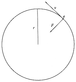
Fig. 2.12
The force on an electron circulating in a
magnetic field. The field H is perpendicular to
the plane of the paper; the force ( ev / c )H is
perpendicular to the velocity v and directed
toward the orbit's center.
[40] The factor c is required to write the watchword in electrostatic units, which we use exclusively throughout; H is then in gauss.
In October 1927, an electrical engineer named Rolf Wideröe presented his doctoral dissertation at the Technische Hochschule, Aachen. In it he described experiments based on the cyclotron equation and the transformer principle. By increasing H in time, Wideröe developed an electric force in the direction of v (the transformer principle); and by constructing specially shaped poles for the electromagnet producing H , he made it possible for particles to remain in circular orbit with constant radius (the cyclotron equation). As he observed, to obtain the necessary centripetal and tangential forces from the same electromagnet, its poles must provide a field that is half as strong at the electrons' orbit as within it—a condition easier to state than to realize.[41] Wideröe called this device a beam transformer; it can be applied practically only to electrons , which, because of their small mass, can attain useful energies under the electric force produced by the time change in H. Evidently the entire acceleration must be accomplished during that part of the cycle of the alternating current energizing the electromagnet in which the electromagnetic force acts in the desired sense.
That is the theory. In practice even the partial cycle was more than Wideröe could use, since he did not succeed in holding his electrons to circular orbits within the evacuated glass doughnut in which he tried to accelerate them. The best he could do, even with several extra coils arranged to compensate for unevenness in the H field, was to guide the electrons around a circuit and a half before they ran into the walls of their doughnut.[42] He thus confirmed the prediction of his former professor, Wolfgang Gaede, an expert in vacuum technology, who had refused to allow the project in his institute at the Technische Hochschule in Karlsruhe on the ground that it was sure to fail. That had driven Wideröe to Aachen, to the more optimistic Walter Rogowski, an expert on cathode-ray tubes and oscilloscopes. As Wideröe later explained
[41] Wideröe, 1928, in Livingston, Development , 107. A magnetic field H perpendicular to a circle of radius r and changing at the rate of dH/dt within the circle gives rise to a tangential electric force (er /2c ) (dH/dt ) and hence to a tangential acceleration dv/dt = (er /2mc ) dH/dt . To balance the resultant increase in "centrifugal force," a changing field H' at the orbit of magnitude (er/mc ) dH'/dt is required by the cyclotron equation. Hence H' = H /2.
[42] Livingston, Development , 113; Wideröe, Europhysics news, 15:2 (1984), 9.
his failure to implement his idea, which had come to him as early as 1922, "The theory of the stabilizing forces acting on the orbit had not yet been developed sufficiently."[43]
No more did the electrical vortex succeed in Cambridge, where Walton tried to implement Rutherford's suggestion of acceleration in the "electrodeless discharge." Here electrons in an evacuated tube without electrodes serve as carriers of the secondary current, the primary being generated in a coil wrapped around it. A supplementary magnet supplied the additional H field, which, according to Walton's detailed and correct calculations, would hold the electrons to a tight circular path within the tube. Walton charged a condenser to 40 kV and discharged it through the coil, setting up oscillations that produced the required varying magnetic field. If all went as calculated, the electrons would attain an energy of 536 keV in a quarter of a cycle. They declined to be regulated, ran into gas molecules, and scattered into the tube wall. Walton gave them up and joined Cockroft in multiplying voltages.[44]
The idea was so good and so obvious that several other physicists flirted with it before Cockcroft and Walton's success with straight tubes and high voltages in 1932. The friendly rivals from South Dakota each tried his hand. Working with Breit, Tuve set up an apparatus similar to Wideröe's, but independently of Wideröe. Tuve and Breit made an important improvement by injecting the electrons into their accelerator at high speeds via an electron gun and claimed to have obtained an acceleration to 1.5 MeV, but they nevertheless ended no more successfully than Wideröe; "No provision has been made [they wrote] to repeat the process very often." Lawrence thought that he could correct the fault of Walton's design, which did not make sufficient provision for axial focusing, with extra coils to create a field that would drive errant electrons back to their orbital plane. He had his assistants realize his design. On June 10, 1931, he tried it, with no better luck than his predecessors. The same success would have attended the efforts of Leo Szilard, had he attempted to make flesh the transformer-accelerator for which he applied for a
[43] Wideröe, Zs. angew. Phys., 5 (1953), 187.
[44] Walton, Cambr. Phil. Soc., Proc., 25 (1929), 469-81. Cf. Kerst, Nature, 157 (1946), 90–3, and Walton in Hendry, Cambridge physics , 51.
German patent in January 1929.[45] There were other patents as well. One of them, secured by Max Steenbeck, a physicist at the laboratories of the Siemens electrical company in Berlin, perhaps referred to a machine that worked.[46]
The method can be made to work. After a decade's experience in focusing beams of fast particles in other sorts of accelerators and in electron microscopes, physicists managed to construct a magnetic system capable of steering and speeding electrons on circular orbits within evacuated tubes. Szilard proposed to have a try in 1938, in collaboration with a physicist at the Clarendon Laboratory at Oxford, James Tuck; their unimplemented design was perhaps the most promising put forward before the first conspicuous success. That was achieved in 1939 and, on a larger scale, in 1940 by Donald Kerst at the University of Illinois.[47] He had the assistance of a former student of Oppenheimer's, Robert Serber, in computing the motions of the electrons. The business continued at General Electric's research laboratory, where a machine for 22 MeV and then for 100 MeV came into existence during the war. Just after the war, Kerst's "betatron" had an important influence on machines built in Berkeley.[48]
Resonance Acceleration
Wideröe had a second failure to announce in completion of his thesis. This one involved the acceleration of heavy ions by modification of a technique proposed, but not implemented, by a Swedish physicist, Gustav Ising. In Ising's plan, positively charged particles fly down a straight evacuated glass tube through a series of hollow cylindrical electrodes, each separately connected to one pole of a spark gap in an oscillatory circuit (fig. 2.13). The particles are drawn from the source into the first electrode when
[45] Breit, Tuve, and Dahl, CIW, Yb, 27 (1927/8), 209; Lawrence to Cottrell, 10 June 1931 (RF/1944/RC Misc); Szilard, CW, 1 , 555–61.
[46] Slepian, U.S. patent 1,645,305 (1922); Smith (Raytheon), 2,143,459 (1931); Steenbeck, 2,103,303 (1937), German patent 698,867 (1935), and Nwn, 31 (1943), 234–5; Wideröe, Zs. angew. Phys., 5 (1953), 199; Lawrence to A.F. Maston, 16 Feb 1938 (15/17A).
[47] Szilard, CW, 1 , 568–81; Szilard to Tuck, 21 Oct 1938 (SzP, 17/198); Kerst, PR, 60 (1941), 47–53, and Nature, 157 (1946), 93–5.
[48] Serber, PR, 60 (1941), 53–8; E.E. Charlton and W.F. Westendorf, Jl. appl. phys., 16 (1945), 581–2.
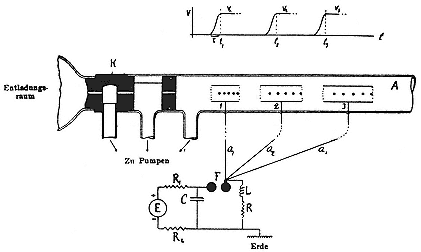
Fig. 2.13
Ising's proposal for a linear particle accelerator. The high-frequency field is
supplied by a discharge across the spark gap F; K is the cathode; a1 , a2 , a3 ,
connections to the drift tubes. Ising, Kosmos, 11 (1933), 171.
its potential has the correct sign and size; while in it they feel no electrical force; on escaping from it they are again accelerated, the direction of the field in the gap between the first and second electrodes having meanwhile altered to the correct sense. The business in principle can be continued through any number of gaps and electrodes.[49]
Wideröe turned to Ising's method after failure of his protobetatron in the hope of having something that worked to describe in his thesis. He replaced the old-fashioned spark vibrator with an up-to-date vacuum-tube oscillator, and theory with practice. He contented himself with only two accelerating steps, which did indeed give the ions twice the energy they would have gained from falling through the maximum potential across the oscillator.
[49] Ising, Arkiv för matematik, astronomi och fysik, 18 (1924), 1–4, and Kosmos, 11 (1933), 170–3.
Nevertheless Wideröe regarded his process as unpromising. He was not interested in particle accelerators, but in what he called "kinetic-voltage transformers," devices for generating currents of high-energy particles useful to engineers. He got currents so small, however, that he despaired of realizing anything much above a milliamp, which ruled out his invention as "a technical generator for high direct voltages."[50] But so puny a flow, of no consequence to engineers, was enough and more than enough for physicists, for, as we know, a milliamp of the right sort of particles exceeds the output of alpha rays from eighty kilograms of radium.
In Wideröe's linear accelerator (fig. 2.14), or "linac" to use the later term of art, sodium or potassium ions from the heated filament at A fall through 20 kV across the gap I when the oscillating potential Ub reaches its maximum negative value on the metal tube BR. In the time the ions float through the tube, which shields them from electrical forces, the potential on it switches to maximum positive value, and the emerging ions drop through 20 kV across gap II. On emerging from the grounded tube S they move under an electrostatic force between the plates at K to strike the fluorescing screen P a distance a below the axis. From measurement of a , Wideröe could confirm that the ions at P had energies of 40 keV. Much higher potentials could be reached, he thought, by multiplying the number of steps, increasing the voltage Ub , and using heavier ions.
This last consideration, which is perhaps not obvious, played an important role in the early history of accelerators. Wideröe's primary improvement over Ising, using a vacuum-tube oscillator to generate the high-frequency potential Ub (the spark gap in fig. 2.14 is for calibration, not generation), avoided the wide band and inconstant energy of the spark circuit, but brought a limitation of its own. It could not operate effectively above a frequency of 107 Hz, or about ten million oscillations a second. It was this limit that directed Wideröe's attention to heavy ions rather than to protons. A singly charged ion of mass AmH (mH is the mass of the hydrogen atom) has a velocity of about

[50] Wideröe in Livingston, Development , 93, 106, and in Europhysics news, 15:2 (1984), 9.
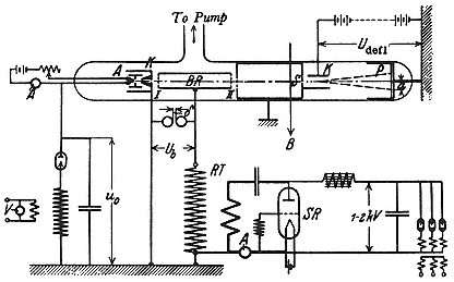
Fig. 2.14
Wideröe's linac for acceleration of heavy ions. The high-frequency field is
supplied by the circuit containing the tube SR. Livingston, Development , 102.
In the last steps of its acceleration it would travel

Wideröe's thesis was published in the issue of the Arkiv für Elektrotechnik of December 17, 1928. On the very same day—the resonance is scarcely credible—Szilard applied for a patent on a similar device at the Reichspatentamt in Berlin. In contrast to the engineer, the physicist explicitly intended his machine to accelerate particles that might disintegrate atoms; as Szilard later explained himself, he rightly saw that the nucleus was the frontier in physics and wrongly guessed that its disintegration would lead quickly to "practical application of very great importance." But he was also busy preparing an application for a British patent on a scheme of refrigeration that he and Einstein had invented, and he
devoted little care to the practical details of his linac. Its principle appears from figure 2.15: ions accelerated between the anode 13 and the perforated cathode 11 enter the accelerator tube 9 sectioned by the grids 1, 2, . . . 6. At S is an oscillator, one of whose leads supplies the odd-numbered grids and the other the even-numbered, which are therefore 180° out of phase with one another. In the ideal case, an ion passes through a grid only when all the grids instantaneously reach zero potential and when the potential is rising on the grid just passed and falling on the grid next in line. The ions are not shielded from the ac field by metal cylinders, as in Wideroë's version, and no doubt the wires in the grids would thin the beam to uselessness long before it had passed the 100 grids that Szilard specified for acceleration to 2 MeV. He planned to work at a hundred million cycles per second, but did not say where he would procure an oscillator. The patent for the linac was not granted.[51]
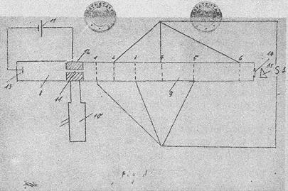
Fig. 2.15
Szilard's linac. The rf oscillator S is at the far right; the source is roughly
indicated by the circuit 11, 12, 13. Szilard, CW, 1 , 553.
[51] Szilard, "Beschleunigung von Korpuskeln," in CW, 1 , 545–53; Szilard to Fermi, 13 Mar 1936, ibid., 729; cf. Weart and Szilard, Szilard , 11.
Another inventor, perhaps independent, of the Wideröe linac was Jean Thibaud, a young physicist who worked with classic radioactive substances in Maurice de Broglie's private laboratory in Paris. Impatient with what nature and radiochemistry provided, Thibaud hoped to reach 10 MeV in small steps; he managed to get to 145 keV by pushing positive ions through no fewer than 11 successive gaps between cylindrical electrodes with an oscillator going at 3·106 Hz. To proceed to alpha-particle energies, however, to compass "the liberation of intra-nuclear energy, an outcome of undoubted general utility," Thibaud recognized that he would need a tube ten meters long and a very powerful and dangerous oscillator, capable of handling 100 kW. "To avoid these difficulties," he said, "I have tried another method."[52] It was the method of the cyclotron. Thibaud did not disclaim credit for its invention or for making it operate independently of Lawrence.[53]
The cyclotron solved the problem of tube length and made possible the resonant acceleration of protons and other light particles. In it the ions spiral out from the center of an evacuated shallow drum, suffering a kick each time they cross a gap between electrodes arranged along a diameter of the drum (fig. 2.16). Between kicks the particles are maintained in circular orbit by a magnetic field. Several people say that they thought of some such scheme before Lawrence did, but for various reasons did not publish it. Wideröe recalled that one of Rogowski's assistants asked whether the ion beam could not be curled around and made to spiral repeatedly through the same electrode gap. "I answered him, as I remember quite well, that I thought that it might be possible but it seemed relatively impracticable to me and I thought the possibility of hitting the gap again could not be very great."[54] Denis Gabor, later a Nobel prizewinner for something else, thought of the
[52] Thibaud, CR, 194 (1932), 360–2, quotes; Pestre, Physique et physiciens , 70, 78.
[53] Thibaud in Solvay, 1933, 71–5, and in Congrès int. électr., Comptes rendus, 2 (1932), 965, says that he succeeded in November 1930, before unambiguous resonance was achieved at Berkeley.
[54] Wideröe, Jena U., Wiss. Zs., 13 (1964), 432–5; Europhysics news, 15:2 (1984), 9; and interview with David Judd, 21 Sep 1961 (18/24), quote; cf. Paul, Aesth. and sci. , 51. Cockcroft, "Development," 2, hints that Walton may have had the idea of the cyclotron too.
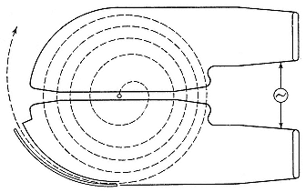
Fig. 2.16
Simplified schematic of a cyclotron, showing the spiral path
of an accelerated ion. Livingston and Blewett, fig. 6.4.
cyclotron as early as 1924, or so he said. But he had other things to do. "My Dr.-Ing. study [on oscilloscopes like Rogowski's] was already in progress, and I let it go." He had another opportunity a few years later. On January 5, 1929, the irrepressible Szilard filed for a patent on, yes, a cyclotron, which he constructed, on paper as usual, by bending the accelerator tube of his linac into a drum sectored by grids. The accelerated particles were cycled back through the grids by a magnetic field. Szilard recalled late in life that he had offered the exploitation of his inventions to Gabor, who then served the Siemens electrical empire, but neither Gabor nor Siemens appears to have seized the opportunity.[55]
The most circumstantial account by a near inventor we owe to Max Steenbeck, who finished up an adventurous career in physics as head of the board for scientific research (Forschungsrat) of the German Democratic Republic. When a doctoral student at the University of Kiel in 1927, Steenbeck conceived the idea of a cyclotron while trying to illustrate certain properties of electrical forces to a particularly stupid student. He worked out a numerical example—acceleration of protons to MeV energies in an orbit of
[55] Gabor to Lindemann, 20 Mar 1956 (FAL, D/80); Allibone, Roy. Soc. Lond., Biog. mem., 26 (1980), 111; Szilard, "Korpuskularstrahlröhre," in CW, 1 , 554–63; Szilard to W.B. Mann, 27 Feb 1952 (SzP, 95/1092).
20 cm under a magnetic field of 14,000 gauss—exactly the experiment done four years later in Berkeley. It was not tried in Kiel. An assistant to Walther Kossel, one of Steenbeck's professors, said it would be too costly; the other professor, Hans Geiger, said that it would be too risky. Before finishing his degree, Steenbeck went to work for Siemens in Berlin. He told his co-workers what he had in mind. They insisted that he publish the idea, no doubt as a precaution for possible future patent applications. Steenbeck agreed, but reluctantly, since the calculation was so elementary. His chief returned his manuscript with a note that he wished to speak further about it. Steenbeck interpreted the note as dissuasion (the chief had probably intended only to request a patent search) and, following his inclination, dropped the matter. Siemens lost the cyclotron again.[56]
These several anticipations of practical resonance accelerators do not detract from, but rather enhance, the achievement of Ernest Lawrence. As Szilard said of Lawrence's success, "The merit lies in the carrying out and not in the thinking out of the experiment."[57] Lawrence came across Wideröe's paper around or before April 1, 1929, while glancing through current journals. (The relevant issue of the Archiv für Elektrotechnik reached the University library on January 23, 1929.) This inspirational encounter may seem, and is said to have been, a matter of chance. The library had just opened a subscription to the Archiv , Wideröe's issue being only the fourth received; the Archiv catered primarily to "engineers working scientifically at electrotechnology" and to physicists only in so far as they took an interest in technical problems; and the Archiv was written in German, a language that Lawrence did not understand. The historian, who seeks the causes of things, prefers to think that Lawrence sought the journal for a definite purpose. Lawrence and Beams had cited an article in the Archiv by Rogowski and others in their paper on Kerr cells; similar references later appeared in theses by Lawrence's students and in a paper he wrote with one of them.[58] It may well be that Lawrence
[56] Steenbeck, Jena U., Wiss. Zs., 13 (1964), 437, and Impulse und Wirkungen , 556.
[57] Szilard to O.S. (Otto Stern?), n.d., in Szilard, CW, 1 , 728.
[58] Beams and Lawrence, JFI, 206 (1928), 176; theses by Washburn and by Dunnington (1932); Lawrence and Dunnington, PR, 35 (1930), 396–407; Dunnington, PR, 38 (1931), 1511, 1545. Intended audience and date of receipt of theWideröe issue appear from the cover of the copy in the Berkeley library.
asked the library to subscribe to the Archiv . He later told Wideröe that he had picked up the issue with the fateful article to pass the time at a boring meeting. Having this succor to hand was not a matter of chance.[59]
Lawrence later gave another explanation. He said that in 1928, when he moved up, and far, from assistant professor at Yale to associate professor at Berkeley, he decided to shift his attention from the effete and played-out photoeffect to the robust new field of nuclear physics. His interest in apparatus drew him to the problem of high-voltage machines. He was already familiar with Tuve's struggle with the Tesla coil and had decided that a million volts could be reached directly only with great difficulty and large apparatus. He would have looked through the Archiv for exactly what he found there, a low-potential way to high energy. Lawrence would soon be building machines rated by his contemporaries as gigantic; but he recommended his first magnetic resonance accelerator as needing only "relatively modest laboratory equipment."[60]
It is sometimes said that Lawrence's cyclotron is Wideröe's two-step bent into a circle. The proper analogy to Wideröe's apparatus, however, is a single ring, within which the ions circulate under a magnetic field H (which Wideröe did not require) as they accelerate from periodic knocks, from the high-frequency field F . To shield the ions between knocks, each of the electrodes has to fill almost half the ring. As the ions speed up, they come to the accelerating gaps between electrodes at shorter and shorter intervals; to remain in step with them, the frequency of the field must increase. Similarly, H must grow to keep the ions on their circle. Such a system was then not practicable. It became the dominant method after the war when implemented in, among other machines, the Bevatron, in the sixth generation of Berkeley cyclotrons.
[59] Wideröe, Jena U., Wiss. Zs., 13 (1964), 432–5. The date April 1 appears in a formal statement by Thomas Johnson, 15 Sep 1931 (10/1), written for possible use in patent fights; Lawrence says "early in 1929."
[60] Lawrence, "Nobel lecture," in Livingston, Development , 136–7; Lawrence and Livingston, PR, 40 (1932), 20, in ibid., 119, quote.
Lawrence saw that a looser analogy to Wideröe's ion accelerator might be possible with constant control field H and oscillator frequency f . The possibility appears from the cyclotron equation (2.1): the frequency of rotation of an ion of charge ei , mass mi , in the field H is independent of the radius of the orbit :

It appears that nature conspires in favor of cyclotroneers. Taking, then, not an annular tube, but a shallow drum or cylinder, as the playground of the ions, Lawrence worked out, on paper only, the scheme indicated in figure 2.17. The iconographer might consider it a combination of Wideröe's circle for electron acceleration with his mechanism for kinetic voltage transformation, a creative misunderstanding abetted and even made possible by Lawrence's inability to read Wideröe's text. "I merely looked at the diagrams and photographs," Lawrence said, in accepting the Nobel prize for his invention.[61]
In the figure, A and B represent hollow half-cylinders of metal, which are alternately charged to a maximum of around 10 kV by a radio oscillator. The close connection with Wideröe appears in, among more obvious features, Lawrence's retention of the word "tube," which Wideröe used appropriately for his straight glass accelerating vessel, for the cylindrical, metallic tank of the cyclotron.[62] "Cyclotron," perhaps Lawrence's first term for his invention, also echoed the notion of tube, in analogy to "radiotron," "thyratron," and "kenotron." (In formal parlance, Lawrence insisted upon "magnetic resonance accelerator;" "cyclotron" rose from slang to the official name in 1936.)[63] To return from the name to the substance of things: Ions liberated in the gas above a filament near the center of the cyclotron enter the gap between the
[61] Livingston, Development , 137.
[62] E.g., Livingston, Production , 11; Lawrence to Livingood, 18 Feb 1932 (12/11).
[63] McMillan to L.D. Weld, 8 May 1952 (12/31); Lawrence to Tuve, 23 Sep 1933 (3/32), introducing "cyclotron;" to Cockcroft, 26 Jan 1935 (5/4), to Bainbridge, 6 Feb 1935 (2/20), to Johnson, 10 Jul 1935 (10/1), to Chadwick, 31 Jan 1936 (3/34), still a nickname; Henderson to Lawrence, 6 May 1935 (9/16), and Lawrence, McMillan, and Thornton, PR, 48 (1935), 493, "a sort of laboratory slang."
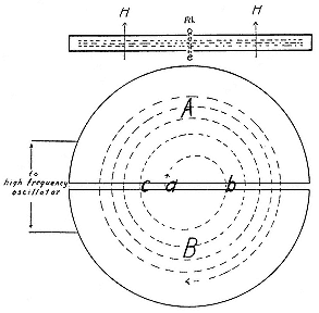
Fig. 2.17
Schematic of the cyclotron. The circle shows the
meridian plane; ions enter at a, accelerate as they cross
the gap at b, c, etc., between the two dees A, B. The
inset at the top shows the vacuum chamber or "tube"
in elevation; H the magnetic field, "fil" the ion source;
the dotted lines indicate particle orbits. Lawrence
and Livingston, PR, 40 (1932), 23.
cylinders when the electric force there can pull them in the direction shown by the arrow at a . On entering A , which shields them from the radio-frequency (rf) field F , the protons revolve in a semicircle ab under H , which is perpendicular to the plane of their orbit, and reemerge at b just when F has reversed itself to pull them into B . The acceleration across b brings the ions into a wider semicircular orbit bc within the shielding electrode B , whence they emerge at C again in step with the rf field. They gradually spiral out under the guidance of H , acquiring 10 or 20 kV from F at each crossing of the gap, and so reach the circumference after a hundred or so turns with an energy of a million volts.[64]
[64] That Lawrence thought out the general principles of the cyclotron in roughly this form during the spring of 1929 appears from the testimony of Johnson (10/1).
Thus the theory. There were reasons to doubt the possibility of its implementation. Only an inventor could think that the beautiful synchronization could last, that the ions could be kept going for one hundred turns without colliding with other molecules or flying from the median plane into the walls of the electrodes or going astray in crossing the gap. Lawrence planned to put his hollow electrodes, or dees as they were later christened, inside a very good vacuum, which would reduce the average distance between collisions to about the length of the spiral path; but that brought the problem of maintaining vacuum seals under the stresses created by the radio-frequency field and the guiding electromagnet. As for keeping the ions in the median plane through the dees, that appeared to be, and for a time was, the greatest problem of all. But here again nature unadorned favored the cyclotroneer.
Lawrence did not move quickly to implement his plans. No doubt the difficulties just described, and the refusal of his friend Thomas Johnson of the Bartol Foundation, then teaching in Berkeley, to join him in the work, gave him pause. But he had a strong positive reason for shelving the idea. He had spent the time since his arrival at Berkeley in the late summer of 1928 building up apparatus to continue his studies of the photoeffect. He had three doctoral students, "a relative importance . . . that I could never have attained at Yale in years," and a need to get results, to justify the reputation for clever and productive experiments that he had brought, and that had brought him, West.[65] One of his students, Niels Edlefsen, confirmed a curiosity earlier studied by Lawrence, that the probability of ionization of potassium vapor increases with the frequency of the light after reaching a local maximum at the series limit. Lawrence tossed the problem of explaining the rise beyond the limit over to Oppenheimer, Berkeley's new part-time theorist; it fell to his graduate student Melba Phillips, who took the problem of photoionization in potassium vapor for her thesis. The business was too much for Oppenheimer's people too, a "pandora's box," according to its historian, "of ultraviolet photoabsorption, photoionization, and ARPES [angle-resolved photoelectron spectroscopy]."[66] Lawrence
[65] Johnson, statement, 15 Sep 1931 (10/1); Lawrence to his parents, 16 Sep 1928 and 7 Jan 1929 (10/38).
[66] Lawrence to Hull, 30 Aug 1928 (7/28); Lawrence and Edlefsen, PR, 33(1929), 265 (abstract of paper for APS meeting, 8 Dec 1928); PR, 33 (1929), 1086–7 (abstract, APS meeting, 18–20 Apr 1929); PR, 34 (1929), 1056–60 (rec'd 28 Aug 1929); M. Phillips, PR, 39 (1932), 552, 905–12; Jenkin, Jl. spect., 23 (1981), 256–60, quote.
continued the experiments and found excitement, if not hope, in the box. "The longer I am in scientific research work," he wrote his parents, "the more fascinating it becomes."[67]
In January 1930 Lawrence began to look more favorably on his "proton merry-go-round." He had had two useful stimuli, one reassurance that it might work, the other notice that he might be anticipated. The reassurance came from Otto Stern, the world's expert in the handling of beams of hydrogen atoms, then providentially visiting Berkeley from his base in Hamburg. Stern thought the spiral beam had a chance and urged Lawrence to take it. Lawrence acknowledged the debt: "Probably if you hadn't urged me so strongly I would not have started the development of the method until some time later." And some time later: "It was your enthusiasm one evening during dinner . . . that stimulated me to try the development of the method." The stimulus from competition came from Tuve and company, who in the Physical Review for January 1, 1930, announced that they could operate their Tesla coil under oil under pressure at 5 MV with 120 sparks/sec. Should they succeed in driving alpha particles along at 5 or 10 MeV and at such a rate, they said, they would have radiation equivalent to that from 2,600 grams of radium. They had found the way to high energy, and found it "without much difficulty."[68]
Lawrence did not work alone. It was one of his strengths. From the time of his arrival at Berkeley, he published only two independent research reports, in 1933 and 1935. He accordingly did not attempt to build the merry-go-round himself, but enlisted Edlefsen, who had just finished his thesis on photoionization of alkali vapors; Edlefsen had a teaching assistantship in the Physics Department and reluctantly stayed on to help make the protons spin. By the end of February 1930, work had begun. "I have started an experimental research based on a very interesting and
[67] Letter of 7 Jan 1929 (10/38).
[68] Lawrence to Stern, 12 Sep 1931, requesting statement for possible use in patent litigation, and 6 Feb 1934 (16/49), quotes; Breit, Tuve, and Dahl, PR, 35 (1930), 51; Breit and Tuve, Nature, 121 (1928), 525.
important idea," Lawrence wrote his parents. "If the work should pan out the way I hope it will it will be by all odds the most important thing I will have done. The project has fascinating possibilities."[69] In March he was working "night and day on . . . producing million volt protons without using high potentials. If this turns out it will of course constitute an important piece of work."[70] But it was not turning out.
During the summer of 1930 Lawrence lazed playing tennis while his graduate students, now half a dozen or more, were "making up for my laxity in activity along research lines."[71] Then a breakthrough came. Edlefsen left to become assistant professor of irrigation investigations in the University's Agricultural Experiment Station.[72] In a carefully worded statement, he and Lawrence described their method, implied that it had succeeded, and proposed parameters for an instrument capable of accelerating protons to a million volts. There is considerable doubt that Edlefsen achieved any resonance acceleration at all. But Lawrence wanted to believe and his natural optimism resonated with his enthusiasm. At the end of their statement, which Lawrence read to a meeting of the National Academy of Sciences on September 19, 1930, he let all qualifications go: "Preliminary experiments indicate that there are probably no serious difficulties in the way of obtaining protons having high enough speeds to be useful for studies of atomic nuclei."[73]
[69] Childs, Genius , 146–7 (re Edlefsen); Lawrence to his parents, 23 Feb [1930] (10/38). Stern remembered seeing a preliminary "Magnetapparatur" around March 1930 (Stern to Lawrence, 2 Nov 1931 [16/49]); McMillan, "Brief history," 1, misdates the building of the Edlefsen-Lawrence cyclotron to January 1930.
[70] Lawrence to Akeley, 21 Mar 1930 (1/12).
[71] Lawrence to Boyce, 4 Aug 1930 (3/2); cf. Lawrence to Akeley, 4 Apr 1930 (1/12).
[72] F. Adams to Lawrence, 15 Mar 1930 (7/1).
[73] Lawrence and Edlefsen, Science, 72 (10 Oct 1930), 376–7, in Livingston, Development , 116. The proposed parameters: f = 1.5·10 Hz, H = 15 kG, R (dee radius) = 10 cm.