Plates Section 1
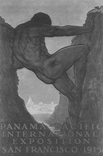
Plate 1.1
"The 13th Labor of Hercules." Official poster of the Panama-Pacific
International Exposition, 1915. Benedict, World's fairs , 114.
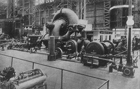
Plate 1.2
Pelton's 20,000-horsepower turbine exhibited at the Panama-Pacific International
Exposition was created for hydroelectric power production in California. Todd, Story,
4 , facing 178.
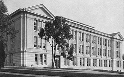
Plate 1.3
LeConte Hall, new home of the Physics Department of the University of
California, around 1930. University Archives, TBL.
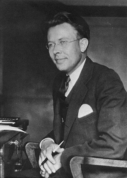
Plate 1.4
Lawrence as a young associate professor. University Archives, TBL.
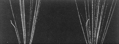
Plate 2.1
Cloud-chamber tracks of the reaction N(a ,p)O. The sheaf of lines are
tracks of alpha particles; the short jagged spur on the far left, the track
of a recoiling oxygen nucleus; the fine straight line running from the
collision fork, that of the ejected proton. Blackett, PRS, A107 (1925),
plate 7, no. 1, facing 361.
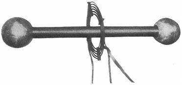
Plate 2.2
Photograph of the Carnegie Institution's Tesla coil. The primary
consists of two or three turns of copper tubing, the secondary of
5,000 to 7,000 turns of silk-covered wire. Breit, Tuve, and Dahl,
PR, 35 (1930), 56.
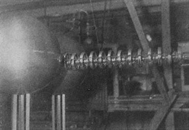
Plate 2.3
Test of Van de Graaff's first setup at the Carnegie Institution. Tuve,
JFI, 216 (1933), 26.
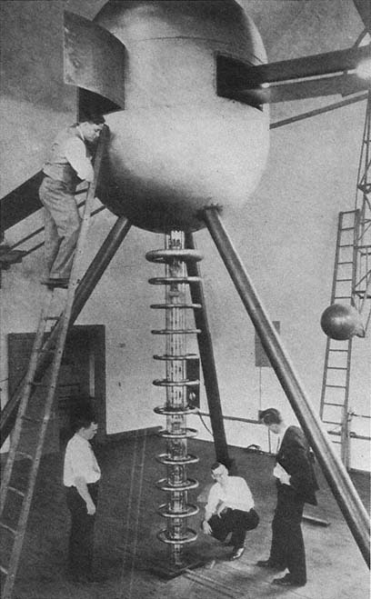
Plate 2.4
The Carnegie Institution's two-meter Van de Graaff; Dahl is on the ladder,
Tuve in the suit. The business end of the discharge tube, deflecting magnets,
and pumps are under the floor. Tuve, Hafstad, and Dahl, PR, 48 (1935), 322.
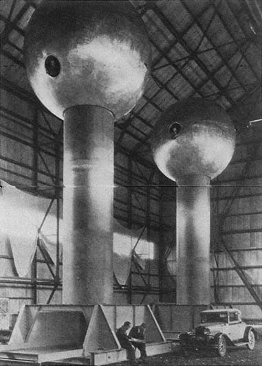
Plate 2.5
Van de Graaff's 15-foot generator at MIT's Round Hill Experiment
Station. The spheres stood 43 feet above the ground; their steel trucks
ran on a railroad track to make possible changes in the striking distance.
Tuve, JFI, 216 (1933), 34.
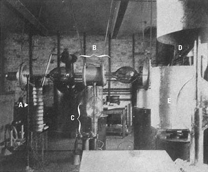
Plate 2.6
Cockcroft-Walton machine. A, capacitor stack; B, rectifying system of
kenotrons with corona shields; C, pumping system; D, transformer system;
E, accelerating tube. Cockcroft and Walton, PRS, A129 (1930), facing 490.
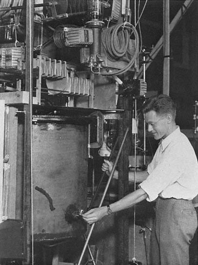
Plate 2.7
David Sloan in the Radiation Laboratory about 1931. LBL.
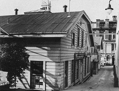
Plate 3.1
The old Radiation Laboratory looking west toward the Campanile. LBL.
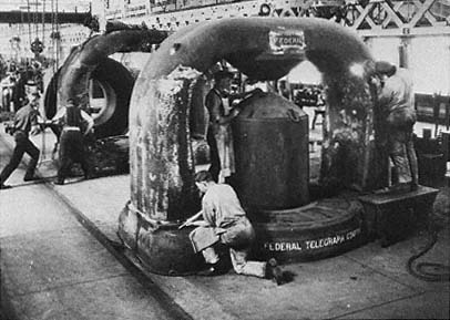
Plate 3.2
1,000-kw Poulsen arcs being machined at Federal Telegraph's plant in
Menlo Park. LBL.
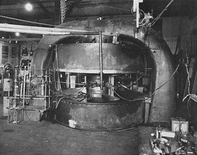
Plate 3.3
The 27-inch cyclotron as installed in the Radiation Laboratory. The glass
vessels supply the source. LBL.
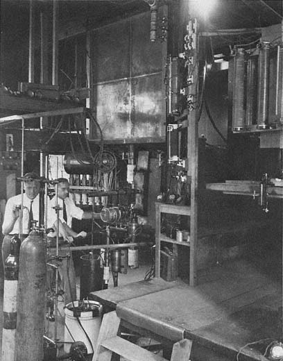
Plate 3.4
David Sloan and J.J. Livingood at work at the Sloan x-ray tube at the
University of California Hospital in San Francisco in 1932–33. LBL.
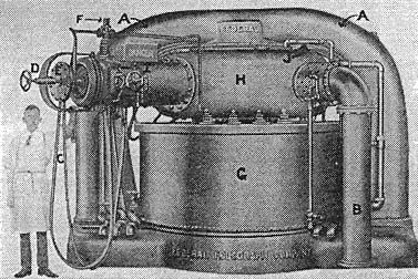
Plate 3.5
Federal's fully assembled 1,000-kV arc generator. A is the magnet yoke;
B, an exhaust pipe; C, the hydrogen supply; G, the tank containing the
coil; H, the tank containing the arc. Heilbron, Museoscienza,
22 (1983), 17.
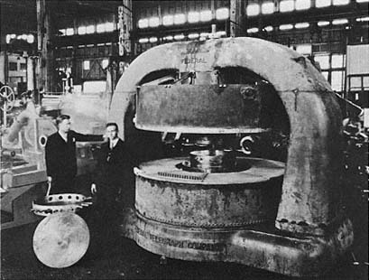
Plate 3.6
Lawrence and Livingston standing beside the Federal Telegraph magnet at
Pelton Waterwheel Company, where it was machined for use in the Radiation
Laboratory. Courtesy of Lois Livingston.
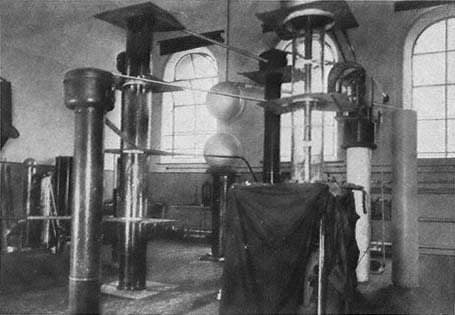
Plate 3.7
Cockcroft and Walton's corner of the Cavendish. The tall transparent cylinder in the
center is the discharge tube; the other cylinders are stacks of condensers and
rectifiers. The curtained box is the observation center. Cockcroft and Walton, PRS,
A136 (1932), 625, plate 11.
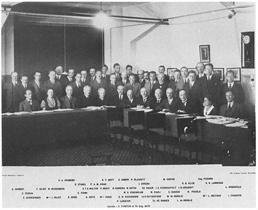
Plate 4.1
The members of the Solvay Congress of 1933. LBL.