Chapter 6—
Geothermal Systems Associated with Basaltic Volcanoes
The most common type of volcanism on Earth is the eruption of basaltic lavas and associated pyroclastic ejecta. The annual rate of magma production for the Earth is ~33.5 km3 ; this estimate by Schmincke (1982) includes both magma intruded into the crust and erupted magma. Basaltic magmas make up ~80%—or 28 km3 of the total volume.
Basaltic magmas originate deep in the mantle and rise quickly to the surface, sometimes carrying solid bits of the mantle along in the form of xenoliths. The lower SiO2 content and higher temperatures of these low-viscosity magmas (most are near 1200°C) allow them to rise buoyantly through narrow dikes in the crust. Unless the magmas have pooled in the shallow crust, as is the case below calderas of most basaltic shield volcanoes, they quickly lose their heat after eruption. Delaney (1987) pointed out that if they are isolated and have fed only a monogenetic cone, basaltic dikes do not provide sufficient long-term crustal heat to drive a geothermal system.
The utility of a basaltic system as a geothermal heat source depends on the rate and volume of intrusion and eruption, which in turn is dependent on the tectonic setting. Basalts erupted along continental rifts can provide a significant heat source if extension rates along those rifts are high and the crust is thin. In many continental rifts, extension rates are low; consequently, eruptive (and intrusive) rates are low and vents are widely spaced in time and space. The narrow dikes feeding these vents cool quickly; however, many such areas of extension may contain geothermal systems that result from the deep circulation of meteoric waters in zones of elevated heat flow.
Vast basalt plateaus present on most of the Earth's continents were formed during periods when lava flows that were tens of meters thick and hundreds of kilometers long filled large basins. Most of these plateaus are old; the most recent major event formed the Columbia River Plateau of the United States during an eruption of 2 × 10⁵ km3 of basaltic lavas between 17 and 6 m.y. ago (Waters, 1961). Plateau basalts like those covering large areas of the north-western United States exhibit no high-temperature geothermal potential.
Basaltic volcanoes within regions of active extension may contain promising geothermal systems. Such regions include the mid-oceanic ridge spreading centers and associated very high temperature hydrothermal systems that cover large areas but are mostly submerged. Where these systems emerge from the sea, as they do in Iceland, numerous high-temperature geothermal systems are accessible. Other basaltic volcanic fields that have excellent potential for geothermal development are the mid-plate oceanic islands like Hawaii, where eruptions occur along rifts associated with large slump blocks that are adjacent to the unbuttressed volcano flanks (Fig. 6.1; Fornari and Campbell, 1987). Continued intrusion and eruption is required to maintain these thermal sources. For example, the upper east rift of Kilauea Volcano on Hawaii has been erupting steadily since observations began in the early 18th century AD Decker (1987) reported that this rift has widened by ~4 m over a 19-year period as a result of 20 intrusions into the summit and the east rift. Christiansen (1987) determined that for every 1 m3 erupted at Kilauea, 2 m3 is intruded. At this rate of extension and intrusion, there is a dependable source of heat to drive hydrothermal systems for some time to come.
The success of geothermal development in basaltic volcanic fields is dependent on an understanding of aquifer locations and regional groundwater movement. Many basalt units in the upper 1 or 2 km of crust are fractured and jointed; they serve as excellent aquifers if they have not been sealed by secondary mineralization. Ash beds, fine-grained sedimentary rocks, and soils interbedded with lava flows often form aquitards for these volcanic aquifers or reservoirs.
Scoria Cones and Tuff Rings
One of the most common subaerial volcanic landforms on Earth is the scoria or cinder cone. Scoria cones are usually formed during single eruptions of basaltic or basaltic-andesitic magmas. Construction of a scoria cone commonly follows the opening of a narrow fissure, a short period of lava fountaining, and (sometimes) a lava flow (Foshag and Gonzalez, 1955; Budnikov et al ., 1975). Soon after the eruption begins, effusive activity is concentrated at one or more points along the fissure. Strombolian or Vulcanian eruptions, consisting of the explosive ejection of bombs, blocks, and ash, continue intermittently for weeks to years. During this period, one or more cones develop through a process of ballistic
Fig. 6.1
(a). Schematic cross-section of the lithosphere beneath kilauea Volcano. The magma ascent
funnel is shown as a region of extensional fractures and magma batches migrating from the
asthenosphere. Variations in stress orientation from the lithosphere and volcanic edifice are shown.
(Adapted from Ryan, 1987a, b.)
(b) Simplified block diagram of the east rift zone of Kilauea Volcano. In one interpretation,
stresses that cause rifting are related to a gravitational collapse of the island's flanks, which allows
intrusion and further widening by dike complexes (A). Other interpretations (B) show the rise of
magma toward the summit of the shield; this movement, cutting across the listric faults, may have
only a minor effect on dike distribution.
(Adapted from Decker, 1987.)
deposition and subsequent slumping when scoria deposits that form the cone exceed the angle of repose, as is shown in Fig. 6.2(a) (McGetchin et al ., 1974). The cone consists of unconsolidated and sometimes welded scoria, blocks, and bombs that make up thick beds dipping outward from the vent at the angle of repose [Fig. 6.2 (b)]. Craters in scoria cones are occasionally modified after they are filled with lavas; in some cases, when leaks develop in the crater walls, dikes and sills penetrate the surrounding scoria deposits (Gutmann, 1979). Lava flows can also erupt from the cone flanks or overflow the crater rim.
Considerable heat is released during the eruptions that produce a cinder cone and its associated lavas. Scandone (1979) estimated that during the 8-year-long eruption of Parícutin in Mexico, 1309 × 106 m3 of tephra and 700 × 106 m3 of lava were erupted; the associated thermal energy was 2.75 × 10¹⁸ J (0.66 × 10¹⁸ calories). This is a substantial amount of heat, but it was deposited above the ground surface and therefore was lost through radiation and convection of heated rain water in the cone.
If rising magma intersects an aquifer or shallow surface water, the resulting volcanic structure will be a tuff cone or tuff ring rather than a cinder cone (Heiken, 1971). Tuff rings are broad, low rings composed of well-bedded, fine-grained tuffs in plane beds and cross-bedded surge deposits [Fig. 6.2 (c)]; poorly exposed tuff ring deposits are often mistaken for fine-grained sedimentary rocks (Fisher and Schmincke, 1984). During the formation of tuff rings by phreatomagmatic or hydrovolcanic eruptions, pyroclastic debris are deposited at relatively cool (~30°C) temperatures because most of the heat is lost in the steam that drives these explosive eruptions.
Most cinder cone fields were constructed by many small-volume eruptions from widely spaced vents, and they do not provide the thermal mass required for a high-temperature geothermal resource. In such areas,
Fig. 6.2
(a). In this diagram of the four major stages in the development of a scoria cone, the numbers refer to
deposits from corresponding eruption stages; only one-half of the cone is shown. During stage 1,
a low-rimmed pyroclastic ring is composed of scoria-fall beds and ballistically emplaced blocks and
bombs. During stage 2, the ring reaches the angle of repose for unconsolidated clastic material;
slumping and avalanching of scoria begins; and the outer slopes of the cone are covered with talus.
In stage 3, the original rim of the cone is destroyed by inward migration of the talus pile. During
stage 4, the talus apron reaches the ballistic limit of the ejecta. The many sizes and shapes of scoria
cones depend on the stage reached as the eruption ended. It is also possible for the crater to fill with
a lava lake and for lava to then spill out of the crater and stabilize the cone slopes.
(Adapted from McGetchin et al ., 1974.)
Fig. 6.2
(b) Cross section of the Rothenberg scoria cone in Germany. Scoria cones are the Earth's
most common volcanic landform above sea level. (Adapted from Houghton and Schmincke, 1989.)
(c) Cross section of a tuff ring formed by the phreatomagmatic eruption of a basaltic magma.
1 = country rock; 2 = explosion breccia; and 3 = bedded tuffs of the tuff ring. Tm = maximum
thickness of the tuff ring at crater rim; Wr = rim-to-rim diameter; We = crater diameter
(excavation width); qm = maximum outward dip of tuff beds; Lr = tephra runout distance; and
De = excavation depth. Tuffs characteristic of tuff rings and tuff cones are generally fine
grained; most of the ash and lapilli were deposited by pyroclastic (base) surges and not by
fallout. Magma volumes and compositions for scoria cones and tuff rings can be identical.
The differences are caused by the interaction of magma and water, which results in the much
more violent phreatomagmatic eruptions that form tuff rings.
(Adapted from Wohletz and Sheridan, 1983.)
the magmas have risen to the surface from the mantle without forming shallow crustal magma bodies. Crater Flat, in south-central Nevada, has 15 small basaltic centers that were erupted during three phases over a period of 3.7 m.y. (Vaniman and Crowe, 1981). The volumes are small (0.3 to 1.5 km3 for each center), as is the cone density (spacing)—10-3 to 10-4 /km2 . The San Francisco volcanic field is larger: 5000 km2 is covered by a few silicic volcanoes and hundreds of scoria cones. The magma sources for the scoria cones and associated lavas there are deep (15 to 40 km), and volumes of individual eruptions are small (Moore et al ., 1976).
Shield Volcanoes
The giant shields that make up many mid-oceanic-plate volcanic islands may contain geothermal resources. In Hawaii, the shield volcanoes are fed from a central conduit below the summit caldera and from active rifts on the flanks (see the case study of Kilauea Volcano presented in this chapter). Shield volcanoes are constructed of thousands of lava flows (from the sea floor to the summit), which are fed by lateral flow from a summit caldera into dikes along flanking rift zones. Magma erupted from rift vents does not move straight upward from the mantle, but laterally along rifts from reservoirs located below the summit calderas. These lava flows are thin, unless they pond in a caldera, a pit crater, or a valley. When groundwater flowing toward sea level is blocked by dike swarms within active rifts, these "perched" aquifers can supply fluids necessary for a hydrothermal system. Figure 6.3 illustrates the interbedded pyroclastic rocks, paleosols, zones cemented with secondary minerals, and rift dike swarms that form the aquitards confining aquifers within the flanks of shield volcanoes (Stearns and MacDonald, 1946).
Fig. 6.3
Simplified hydrology of a mid-oceanic shield volcano
(Adapted from Stearns and Macdonald, 1946.)
Later in this chapter, we describe hydrothermal systems that have been tapped in shield volcano rift zones. These case studies include geothermal systems currently operating in Iceland and a field being developed along Kilauea Volcano's east rift.
Lava Lakes and Magma Energy—Resources for the Future
Eruptions on basaltic shield volcanoes are often followed by the collapse of summit calderas or pit craters located along the rifts. These craters may be filled with lava from either the eruption that formed them or lava flows that spilled into them during later eruptions. At Kilauea Volcano between 1959 and 1972, eight lava lakes were formed; their thicknesses range from 6 to 180 m and initial temperatures were 1100 to 1200°C. Although these lakes are short-lived (they solidify within a few decades) and potentially hazardous, Colp (1982) has proposed that they be used to develop high-temperature, manmade geothermal systems.
Makaopuhi, Alae, and Kilauea Iki lava lakes in Hawaii have been studied by means of drillholes, geophysical surveys, and thermal models. Kilauea Iki, a pit crater adjacent to Kilauea Caldera, was partly filled with 38 × 106 m3 of lava that formed a lake 110 m deep and 750 m in diameter (Richter et al ., 1970). Data from the 11 holes drilled into the lake over a 16-year-period have indicated that the depth to molten rock has progressed from 4.8 m in 1960 to 45 m in 1976 (Fig. 6.4). The crust has been solidifying at an average rate of 6.7 × 10⁻⁸ m/s (Hardee, 1980). Heat is being released through two zones in the solid crust: a lower, one-phase advective zone and an upper, two-phase convection-advection zone (Fig. 6.5). Temperature measurements indicate a constant temperature of 100°C to a depth of 40 m, below which it increases abruptly to 1070°C at 52 m.
Although many geologists and engineers believe that lava lakes are a potential, short-term thermal resource, the drilling and extraction techniques that would make production wells within these lakes practical have yet to be developed. The difficulties of transferring heat from a lava lake to the surface still must be overcome. For instance, present routine geothermal drilling is limited to temperatures of <250°C. If indeed the technology can be developed, the surface facilities obviously must be portable. At Kilauea Iki, for example, the crater has been partly filled three times since 1832, and it is probable that there will be more eruptive episodes in the near future.
Kilauea Volcano and Kapoho Geothermal Area of Hawaii
The Hawaiian-Emperor Island chain consists of ~107 volcanoes that range in age from 80 Ma at the northwestern end to currently active volcanoes at the southwestern end (Decker et al ., 1987). The islands are remnants of these volcanoes, which rise between 5,000 and 10,000 m above the floor of the Pacific Ocean. The chain was formed as the Pacific plate moved over the Hawaiian hot spot at 9.2 cm/yr (Hawaiian Chain) and 8.6 cm/yr (Emperor Chain) (Clague and Dalrymple, 1987). Subaerial portions of these islands consist of thousands of thin basaltic lava flows and minor deposits of pyroclastic rocks and differentiated lavas. Hawaii, the youngest island in the chain, is made up of five overlapping shield volcanoes, two of which remain active (Fig. 6.6).
The still-active shield volcanoes of Kilauea and Mauna Loa are believed to be made up of a below-sea-level mass of submarine pillow basalt that is interbedded with and overlain by hyaloclastite deposits and subaerial basalt flows. Hill and Zucca (1987) report that under the Kilauea and Mauna Loa shields, the Mohorovicic
Fig. 6.4
Map and cross-section of Kilauea Iki Crater before and after the 1959 eruption. The deep lava lake
has been drilled many times for research purposes and has been the testbed for the U.S.
Department of Energy's magma energy concepts.
(Adapted from Richter and Moore, 1966.)
Fig. 6.5
Models and observations of the thermal history of the Kilauea Iki lava lake. (a) Model of cooling
above a downward-moving thermal front at 2000, 4000, and 6000 days. (b) An early model proposed
to explain the drastic temperature change in the one-phase advective (dry-out) zone. (c) This
summary of the major physical characteristics of the lava lake in 1980 (20 years after the eruption)
shows depth to melt, changes in resistivity, temperature, percent of glass,
and depth (120 m) to the preflow surface (lake bottom).
(Adapted from Hermance and Colp, 1980.)
discontinuity increases from ~10 km (for normal oceanic crust) to 13 and 18 km, respectively. Fast P-wave travel times through rift zones and summit calderas as well as positive gravity anomalies over them indicate that intrusive cores form a significant fraction of these volcanic edifices (Fig. 6.6).
Eight of the youngest and largest islands in the chain make up the State of Hawaii, which is an area of intense urban and agricultural development. A comprehensive evaluation of Hawaii's geothermal resources, conducted by university and federal scientists (Thomas et al ., 1979, 1983), concentrated on calderas and associated rift zones. Much of the work focused on the Island of Hawaii and drew upon the vast research base built by the State of Hawaii, the Hawaiian Volcano Observatory, research drilling programs, and commercial geothermal drilling projects. The report cites an output of 3MWe at the one operating hydrothermal electrical generating plant, which is located at the Kapoho geothermal site on Kilauea Volcano's east rift zone. At this time, a well field is being drilled and a 25-MWe (net) power plant is being constructed in the Kapoho area (Clark and Stewart, 1991).
Migration of Magma and Evaluation of Thermal Sources
As is the case for all hydrothermal systems, geothermal system development in Hawaii depends on an understanding of volcanic heat sources and groundwater. In this area, where there is little surface water and a constant volcanic hazard, geoscientists have achieved a good understanding of both of these crucial aspects. Most of the geothermal exploration on the Island of Hawaii is concentrated on Kilauea Volcano, where the storage, migration, and eruption of basaltic magmas is monitored by the Hawaiian Volcano Observatory's geophysical network.
In this area, magma rises buoyantly along a very irregular network of vertical, roughly cylindrical conduits that are marked at the surface by a caldera. Kilauea Caldera, located at the summit of the volcano, consists of concentric collapse craters, the widest of which is 4.5 by 3 km. Helz (1987) has determined that the picritic (~20% olivine phenocrysts) basalt of the 1959 Kilauea eruption originated at depths of 45 to 60 km and rose to the surface at velocities of 0.58 to 0.77 cm/s; which is fast enough to carry along olivine xenocrysts and aggregates.
Eruptions in calderas and along rifts are spectacular—with lava fountains, fast-moving lava flows, and occasional phreatomagmatic activity—however, most of the magma never reaches the surface but comes to rest in a shallow crustal environment. These magma bodies, located within the uppermost 7 km of the crust, are responsible for the heat that drives geothermal systems on Kilauea. Ryan (1987a,b) addressed the reason most magma comes to rest at shallow levels in the crust in his elegant study on the regions of neutral buoyancy. Ryan integrated seismic and surface deformation data with measurements of the physical properties of rock and magmas under pressure to provide information on the variation of crustal rock densities with depth. Below 9 km, all macrofractures, microfractures, vesicles, and joints are eliminated by bulk compression [Fig. 6.7(a)]. Below 7 km, magma is transported buoyantly within the central conduit and the intensity of hydraulic fracturing is high. Between 7 and 2 km, the in-situ densities of the fractured crustal rock and the magma are similar, and a magma
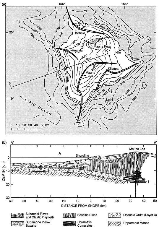
Fig. 6.6
(a) Map of the island of Hawaii shows the major rift-zones of the five overlapping shield volcanoes.
Elevation and depth contours are in 500-m intervals on land and 1,000-m intervals offshore.
(b) This schematic cross-section of the central and western Mauna Loa shield is based on the
P-wave velocity and density models of Hill and Zucca (1987).
body is formed at a point where buoyant rise is no longer possible; the fact that this is an increasingly aseismic region indicates a higher fluid/rock ratio (Fig. 6.7). The center of neutral buoyancy is located at depths of 2.5 to 4.5 km, suggesting a correspondence between the depths at which magma is in mechanical equilibrium with the surrounding rock and the depth of Kilauea's subcaldera magma reservoir. From depths of 0 to 2 km, the deformed and fractured crust allows vesiculating magmas to pass through dikes. As the volcano grows, the summit (subcaldera) magma reservoir and associated rift system is elevated and achieves mechanical equilibrium within the lava shield (Ryan, 1987a,b). The entire igneous system rises with both time and a continuing supply of magma, but it retains the same depths below the volcano's surface. This is an important concept to keep in mind when evaluating thermal sources within shield volcanoes similar to those at Kilauea and Mauna Loa.
Ryan (1987a,b) determined that most magma movement into rift zones from the summit reservoir is at a depth of 3 km—a level of neutral buoyancy. Magma moves rapidly along the rift until the fluid pressure falls below that of the tensile strength of the host rock. Ryan (1987a,b) cites three types of dike formation.
(1) Slow movement of magma, with a gradually enlarging fracture front. The dike top rises toward the surface and the bottom descends at a similar rate.
(2) Rapid movement of magma, during which the dike top rises rapidly and, simultaneously, the base sinks. Subsequent pressure reduction narrows the dike and restricts it to the neutral buoyancy zone.
(3) Pressure differentials within the growing dike form an intrusion shaped like a doubly serrated knife. The "serrations" have amplitudes of 2 to 6 km. Where a rising dike intersects the surface, cracks open and a rift eruption begins, as is depicted in Fig. 6.8.
These models have been developed from data collected over the last 20 or 30 years, when activity at Kilauea volcano has been mostly along the rifts.
A well-exposed analog to Kilauea volcano is the Koolau volcano on Oahu, for which Walker (1986; 1987) described the internal structure. The shield of Koolau was constructed by small but frequent eruptions of basaltic magma. Erosion has eroded the 57-km-long volcano to a depth of ~1 km and exposed the plumbing within its shield. Kailua caldera, located at the southeast end of the Koolau volcano, is analogous to Kilauea Caldera and consists of mainly thick, massive lava flows. It lacks the thin pahoehoe lava flows that characterize the Kilauea shield volcano. Breccias within the 4-km-diameter Kailua caldera may represent either periods of collapse or phreatic blasts. A rift extending northwest from the caldera is composed of ~5100 dikes over its 3.3-km width, as is illustrated in Fig. 6.9. The rift
Fig. 6.7
Earthquake abundance and in-situ density with depth beneath Kilauea volcano.
(a) Distribution of earthquakes beneath Kilauea's summit region, to a depth of 20 km.
The dark pattern refers to the volume beneath the whole Kilauea caldera and the light
pattern refers to the volume beneath only Halemaumau crater. The aseismic
region from 2 to 7 km is believed to have high magma:rock ratios.
(Adapted from Ryan, 1987a.)
(b) In-situ densities of olivine tholeiitic basalt near its liquidus, volcanic shields, and the upper
mantle below Hawaii. The depth region of density crossover coincides with the subcaldera region of
magma storage below Kilauea; based on data from Salisbury and Christensen, 1976; Fuji and
Kushiro, 1976; and Zucca, Hill, and Kovach, 1982.
(Adapted from Ryan, 1987a.)
Fig. 6.7
(c) Schematic diagrams show the evolution of oceanic shield volcanoes such as Hawaii, progressing
from Mokuaweoweo caldera of Mauna Loa volcano (oldest) to the Loihi seamount (youngest).
Low r = low density; Vp = P-wave velocity; and Vs = shear-wave velocity. As the volcano grows,
it carries with it its contractancy profile and regions of fracturing; the region of neutral buoyancy
rises from below sea level to well above sea level.
(Adapted from Ryan, 1987b.)
follows listric faults that dip outward on either side of the Koolau shield. Dikes range in width from <5 to 670 cm, with a median of 53 cm, and typically have glassy, chilled margins and sheetlike cooling joints that are perpendicular to dike margins. These dikes sometimes occur in clusters (or swarms) as wide as 20 m, in which successive members were injected either along the margins or inside preceding dikes. Within such clusters, dikes may make up 100% of the rock.
Most of Hawaii's recent exploration and drilling for hydrothermal development has been along the east rift zone of Kilauea Volcano. The subaerial part of Kilauea is 80 km long and 20 km wide and still growing. [For the most recent compilation of geologic maps, refer to Holcomb (1987)]. Kilauea rises to an elevation of 1240 m above sea level and serves as a topographic barricade to the trade winds and rainfall; as a consequence, the eastern slopes of the volcano are covered with dense vegetation and the southwestern slopes are a desert— an important observation to consider in planning geothermal development. Kilauea is young and very active: 90% of the surface is younger than 1000 years (Holcomb, 1987). Approximately 50% of the volcano surface is covered with lavas that overflowed the summit caldera, but such an event has not occurred for 200 years; 81% of the lava flows are pahoehoe , and aa flows make up a smaller volume. During the last 500 years, periods of sustained summit activity have included only minimal flank (rift) activity. However, when there is little activity at the summit, other than caldera collapse, the flanks are more active.
Kilauea's caldera is actually a collection of nested (but not concentric) calderas, in which the outermost visible caldera is 7.5 by 5.1 km and the innermost (Halemaumau Crater) is 0.9 km in diameter. The subaerial portion of Kilauea's east rift zone is 50 km long and 2 to 3 km wide; the actual rift extends about 50 km further below sea level. Figure 6.10 illustrates the surface manifestations of rift tectonic and volcanic activity: normal faults, open fissures, and pit craters; cinder cones, spatter ramparts, tuff cones, and steaming ground are associated with these features, but are not shown on this map.
Hydrothermal Systems at Kilauea Caldera and Along Its East Rift Zone
A 1.2-km-deep research drillhole, located on the southwest margin of Kilauea caldera, was drilled to a depth just below sea level to test hypotheses concerning the thermal state and groundwater movement near a magma body (Keller et al ., 1979). The drilling operation encountered lava flows as well as a few sills and ash layers. Porosity decreases with depth, which is commonly the result of pore spaces filling with secondary minerals. Permeabilities above the water table are 100 mD to 1 D; below the water table they are <100µD (Zablocki et al ., 1974).
Within the Kilauea well, temperatures of 20 to 30°C are maintained with increasing depth until, at 480 m, the water table is reached. At that depth, temperatures rise rapidly in lavas, which are saturated with brackish water below the water table; the temperatures begin to decrease at a depth of 725 m (Fig. 6.11). Below 725 m, the thermal gradient is conductive and reaches a temperature of 137°C at the bottom of the drill-hole. Zablocki et al . (1974) concluded that if this gradient persists, magmatic temperatures should be found at a depth of 4 km.
Figure 6.12 shows the locations of five deep (>2000 m) and four shallow exploration wells drilled in the Puna District along Kilauea's east rift zone in the 1960s, 1970s, and early 1980s. The first two wells were drilled adjacent to vents of the 1955 eruption, where there is steaming ground. These wells, drilled to depths of 54 and 167 m where the maximum temperatures were 54 and 102°C, respectively, were sited in the unsaturated zone and no geothermal resource was found (Thomas et al ., 1983).
Fig. 6.8
Three-dimensional model of the internal structure of Kilauea volcano. The medium stippled pattern
denotes the structure of the southwest and eastern rift zones that extend outward from the summit
magma reservoir, as well as the main conduit that rises from a depth of 40 km. The reservoir is a lightly
shaded region at a depth of 2 to 7 km. Periodic high-level injection of magma into the rift zones occurs
along the horizon of neutral buoyancy (arrowed pathways) and is associated with the lateral
formation of dikes at 3 km below the volcano's surface.
(Adapted from Ryan, 1987b.)
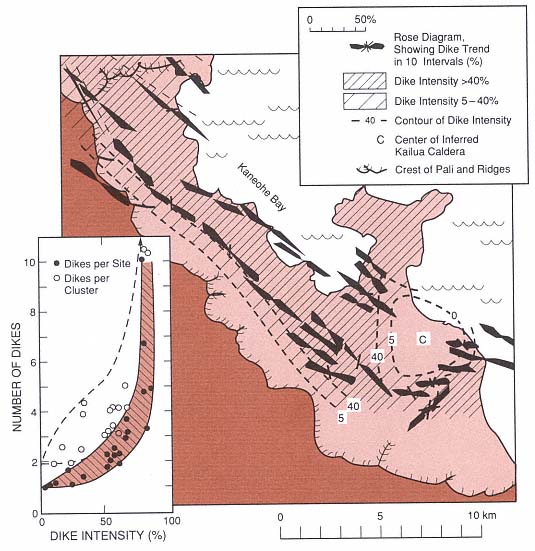
Fig. 6.9
Dike swarms of the ancient Koolau dike complex and Kailua caldera. (the inset shows dike intensity
as well as the number of dikes per cluster and site). This ancient shield caldera and rift zone is
analogous to the modern Kilauea volcano and is used to
interpret the younger volcano's structural framework.
(Adapted from Walker, 1987.)
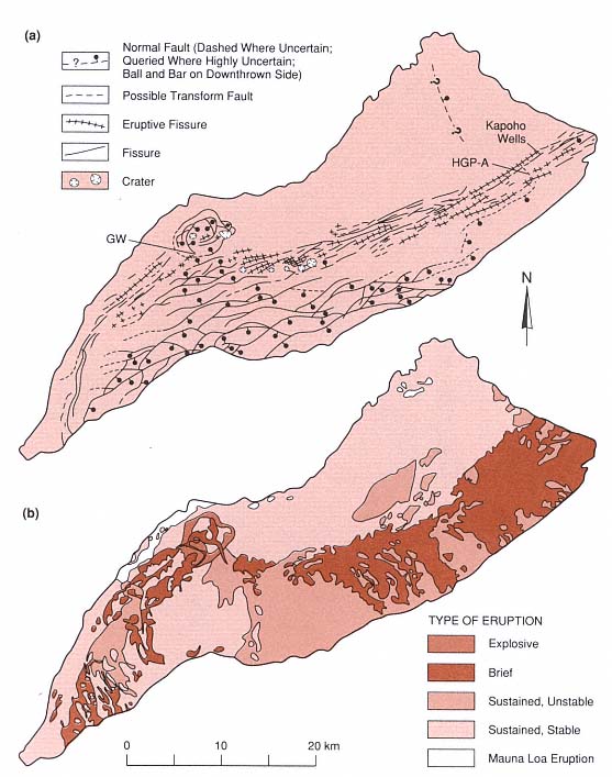
Fig. 6.10
Geology of Kilauea volcano. (a) Structural map depicting Kilauea caldera, pit craters, normal faults,
fissures and eruption fissures. HGP-A is the location of the Hawaii Geothermal Project well in
the Puna District. The Kilauea research drill hole is denoted GW. (b) Map of Kilauea volcano
showing lava flows classified by eruption type.
(Adapted from Holcomb, 1987.)
Fig. 6.11
(a) Cross-section of Kilauea caldera including the Kilauea Research drill hole (GW). (b) Temperature
logs from the Kilauea drill hole. There is no increase in temperature until the water table is reached
at a depth of 480 m. Below 725 m, the gradient is conductive
it reaches a maximum of 137°C at a depth of 1250 m.
(Adapted from Zablocki et al ., 1974.)
Fig. 6.12
(a) The lower east rift of Kilauea volcano indicating the limits of the surface expression of the rift
and the location of groundwater and geothermal wells. Contour intervals are 200 ft. The inset shows
topography, the apparent water table, and self-potential for profile A—A'.
(Adapted from Thomas, 1987.)
In 1976, a government-sponsored well (HGP-A) was drilled near the center of the east rift zone at an elevation of 200 m and ~300 m east of a spatter rampart formed during the 1955 eruption. This well is located near the intersection of the north-east-trending rift and a northwest-trending, right lateral fault mapped by Holcomb (1987). The drillhole is also 28 km west of and 1043 m lower than Kilauea's summit caldera. It was drilled to a depth of 1968 m and has a bottom-hole temperature of 358°C (Fig. 6.13). The reservoir is located in lava flows and dikes, where Stone and Fan (1978) reported three zones of hydrothermal alteration: (a) 675 to 1894 m—montmorillonite, (b) 1350 to 1894 m—chlorite, and (c) 1894 to 1962 m—actinolite and calcite. These authors concluded that the present-day thermal regime is related to recent
Fig. 6.13
Temperature profiles measured in the Hawaii Geothermal Project well HGP-A. The inset is a
conceptual cross section of the lower east rift of Kilauea that depicts fluid circulation across
the rift zone. Thermal waters leaving the rift to the southeast (downslope) form a plume overlying
the colder fluids below. Drilling on the downslope side of the rift would initially encounter hot
fluids but at greater depths would enter cool aquifers.
magma injection. The fluids are slightly saline but have high concentrations of silica and sulfide (Kroopnick et al ., 1978). Thomas et al ., (1983) calculated that the flowing well produces 50,000 kg/hr: 50% liquid (mixed seawater and meteoric water) and 50% steam. An electricity generating plant has been producing 3 MWe . Because the possibility of an eruption close to the plant was considered in its design, most of the equipment is on skids and can be removed if necessary.
At the time of this writing (1991), five production wells have been drilled near HGP-A. Most of these wells are located within the northern edge of the rift, in line
with fractures and a spatter rampart formed during the 1955 eruption and on the slopes of Puu Honuaula, a cinder cone believed to be between 1500 and 10,000 years old. These were drilled to depths of over 2000 m and have bottom-hole-temperatures of 312 to 334°C. The reservoir begins at a depth of ~1200 m and extends to a depth of at least 2250 m; it consists of a basaltic dike complex composed of near-vertical dike swarms, each separated from the other by brecciated wall rock (Clark and Stewart, 1991). The reservoir is overlain by ~750 m of submarine basalt flows with low permeability and by 450 m of subaerial basalt flows, which are permeable and contain an unconfined aquifer (Clark and Stewart, 1991).
The dikes and fractures of the east rift act as guides for fluid flow, allowing hot fluids to rise parallel to the dikes. The rift also dams water from upslope; the apparent water table rises to the near-surface on the north-west side and plunges to a depth of 400 m on the southeast side (Jackson and Kauahikaua, 1987; Thomas, 1987). Much of the potential sea water inflow is also blocked by rift dikes. Within the rift, where there is adequate fracture permeability and depth (~2000 m), the hydrothermal plume can be drilled and developed. Beyond the southern edge of the rift, one well penetrated thermal fluids at shallow depths but reentered cold sea water below the outflow plume from the rift, as is shown in Fig. 6.13 (Thomas, 1987).
Exploration and production drilling has taken place only along the east rift of Kilauea Volcano; this area is accessible and is located on private land (except for the research well that is sited in the National Park). The southwest rift zone of Kilauea and all rift zones of Mauna Loa, Mauna Kea, and Hualalai have not yet been drilled. These resources have been examined only at the surface during the Thomas et al . (1979, 1983) evaluation of the geothermal resources of Hawaii.
Three Geothermal Systems in Iceland: Krafla, Surtsey, and Heimaey Volcanoes
Iceland is located over the Mid-Atlantic Ridge, which is an active spreading center. Regions of active extension and volcanism in Iceland are called the neovolcanic zones and cross the island generally from south-west to northeast. Most volcanic activity occurs along the eastern and western volcanic zones, where plate motion currently averages 1.6 cm/year in either direction and lavas and pyroclastic deposits are erupted at a rate of 0.04 km3 /yr. The largest single historic eruption of basaltic lavas (12 km3 ) occurred in 1783 from the 25-km-long Laki fissure (Sigvaldason, 1974). The active state of this island and the extent of its geothermal resources are reflected in the thermal gradients, which vary from ~160°C/km (heat flow = 300 mW/m2 ) in the fissure swarms to 40°C/km (heat flow = 80 mW/m2 ) in the oldest rocks along the island margins (Pálmason, 1973). Fissure swarms in the neovolcanic zones range from 5 to 10 km wide and are 30 to 100 km long. Each zone consists of nested grabens, where near-vertical normal faults are exposed at the surface. Figure 6.14 illustrates the active faulting, volcanism, and geothermal systems that occur along these fissure swarms.
The economy of Iceland is closely linked to geothermal energy. Half of the population lives and works in buildings heated by geothermal waters. Greenhouses, an important component of the island's agricultural effort, are also heated by hot springs and water from geothermal wells. Many hot water wells have been drilled for direct-use applications, especially around the capitol city of Reykjavik. These waters are pumped from reservoirs located in Tertiary-age interbedded flood basalts and hyaloclastite deposits at depths of 1 to 2 km and temperatures of 86 to 128°C. Hot water is conducted horizontally along the basal contacts
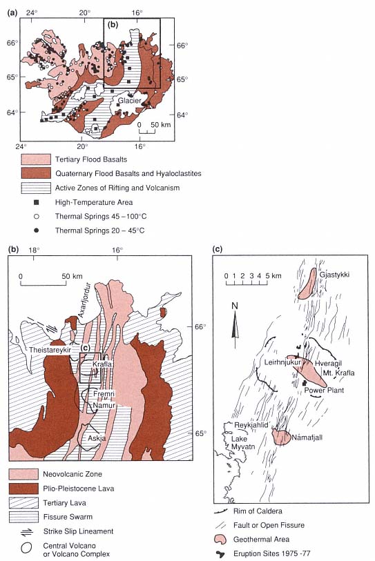
Fig. 6.14
(a) Simplified geologic map of Iceland shows the distribution of
geothermal manifestations and their relation to active volcanic zones.
(Adapted from Fridleifsson, 1979.)
(b) Fissure swarms and central volcanoes of the Northeast volcanic zone of Iceland
(Adapted from Stefánsson, 1981.)
(c) Structural map of Krafla caldera and its active fissure swarms
(Adapted from Stefánsson, 1981.)
of lava flows and vertically along dikes and faults; Bodvarsson (1961) presents hydrologic and chemical evidence that these waters can flow laterally for as far as 50 km.
High-temperature geothermal systems are associated with the young volcanic fields along the active tectonic rifts. Most have temperatures of 200 to 300°C at depths of 1 to 2 km. Bodvarsson (1976) estimated that nearly 400 km2 of Iceland, along the neovolcanic zones, is underlain by high-temperature geothermal systems. The Krafla field, which is representative of these hydrothermal systems, has been developed in and around Krafla caldera in northeastern Iceland, as described in the next section.
Migration of Magma and Dike Formation
Information on the movement, shape, and size of magma bodies below fissure swarms is based on both geophysical measurements during recent eruptions and structural/volcanologic studies of historic eruptions. Magma overpressures result in the beginnings of extension, which in turn lead to magma rise and eruption. Sigvaldason (1987) inferred that during the 1975–1981 Krafla eruptions, magma moved through "holding chambers" at depths of 30, 25, 8, and 4 km. After the eruptions, refilling of these intermediate chambers took ~3 weeks. From the high-level chambers—at depths of 3 to 7 km—repeated lateral magma injections into fissure swarms north and south of the Krafla central volcano initiated a rifting event. [This rifting episode was activated by the subsequent release of tensional stress that accumulated over the plate boundary during the previous 250 years (Tryggvason, 1984)]. The fissure swarm was extended by an 80- to 90-km-long section during this period; the average widening for a fissure during the accumulated 20 discrete events was 5 to 6 m (Tryggvason, 1984). Each extensional event was accompanied by subsidence near the center of the Krafla caldera, which demonstrates the link between the fissure swarms and the high-level chamber below the central volcano.
Tryggvason (1984) determined that the accumulated area of fissure widening during the 1975–1981 Krafla event was ~377,000 m2 . Based on observed ground deformation, he suggested that most of the magma was injected into vertical fissures rather than into sills. Using gravity and elevation measurements, he determined that the volume of magma leaving the reservoir was ~1.75 times that of caldera subsidence. The dike volume (V) is equated with that of magma leaving the reservoir, minus the volume of material erupted. The estimated dike height (h) = ~1.75 V/A, where A = area of horizontal extension by the dike. For the best recorded events at Krafla, calculated dike heights are 2.4 to 2.8 km. The total volume of magma that flowed out of the reservoir into fissure swarms during this episode at Krafla is estimated at 1.08 km3 , of which 1.03 km3 remains in the dikes to become a renewed heat source for the associated geothermal fields. The measured volume of lavas erupted is 0.2 km3 , which is four times greater than the volume predicted. Tryggvason concludes that perhaps the volume estimates of magma leaving the caldera are too low.
Gudmundsson (1986) used his work on the Reykjanes Peninsula of Iceland to develop a method for estimating the volume of magma reservoirs below fissure swarms, as is depicted in Fig. 6.15; his method requires the measurements and assumptions listed here.
· The maximum length for a magma reservoir is taken to be equal to the length of vents in the fissure swarm.
· The width of the reservoir is estimated to be 1.72 times the width of the vents in the fissure swarm; this ratio is based on observations of older dike swarms that are exposed in outcrop.
· A reservoir is taken as an ellipsoid, the volume of which is calculated as V = 4/3 p ah bh ch and the area of which is calculated as A = p ah bh ,
where ah , bh , and ch = the half-width, half-length, and half-thickness, respectively, of the ellipsoid. The half-thickness of the reservoir is calculated by ch = 0.75 V/A, where V = total volume of the magma (both erupted and in dikes).
· The average volume of individual fissure lava flows on the peninsula is 0.11 km3 . Walker (1959) estimated the average volume of a corresponding feeder dike by using the average length of the volcanic fissures (2.2 km), a crustal thickness of 8 km, and an average dike width of 4 m. The estimated volume of a feeder dike here is 0.07 km3 and an average value for ch is 1.5 km (2ch = 3 km). It is likely that only the uppermost 3 km of the reservoir participates in an eruption.
The volume of feeder dikes (~0.07 km3 ) is small, but as a result of intrusions and eruptions every 10 years, the active fissure swarms contain excellent heat sources. Bodvarsson (1976) calculated that in Iceland, heat reaches the surface by conduction (~50%), as erupted magma (~30%), and as thermal waters (~20%).
South of Krafla caldera is Askja-Öskuvatn caldera; Sigurdsson and Sparks' (1978) documentation of the 1874–1875 eruption provides another view of fissuring and dike injection along the fissure swarms. The Askja central volcano straddles a 75-km-long fissure swarm. Magnitude 6 or 7 earthquakes in 1872 marked a new phase of rifting, and by the fall of 1874 the fissure swarm was rifted along a 70-km segment. A graben 1 to 2 km wide was formed, bounded by normal faults with throws of 40 to 60 m south of the central volcano and 10 m north of it. In early January 1975, a major injection of magma into a high-level reservoir was followed by phreatomagmatic eruptions of rhyolitic ash. Caldera inflation was relieved by periodic injections of magma out into the fissure swarms. At the surface, the central fissure is flanked by en echelon spatter ramparts. The Sveinagja lava field covers 30 km2 ; it is
Fig. 6.15
(a) Fractures measured in the western part of the
Thingvellir swarm in Iceland. (b) The width and
throw of three fractures from the Thingvellir
swarm were measured along
the strike of the fissures.
(Adapted from Gudmundsson, 1987.)
located 40 to 70 km north of the Askja-Öskjuvatn caldera and consists of 0.3 km3 of mostly tholeiitic aa and pahoehoe lavas. The estimated volume of intruded magma was 1.5 km3 , which could be accounted for by a single 100-km-long, 5-km-deep, 3-m-wide dike. Fissure widths range from 2.5 to 4 m. In the northern part of the lava field, activity was centralized at an offset in the rift and formed a line of cinder cones.
Brown et al . (1987) used gravity surveys to document the presence of a 20-mGal, north-south-trending anomaly that may correspond with a dense dike swarm below the Öskuvatn-Askja caldera. They also noted that caldera fill is most likely thin and that the caldera's collapse was primarily related to eruptions out along the fissure swarms.
Hydrothermal Reservoirs
Hydrothermal reservoirs in Iceland are usually bounded by lava flow contacts or clay-rich hyaloclastite deposits. Water in aquifers can also pond when dikes act as barriers. By measuring the deuterium content of thermal waters, Arnoson (1976) has shown that the waters are of meteoric origin, although a few systems are charged with seawater. In most cases, water from the highlands percolates into bedrock and flows laterally for distances of as much as 150 km but more usually several tens of km. The water then rises to the surface along dikes or faults. Tables 6.1 and 6.2 summarize potential reservoir rocks and the flow rates through these rocks as sampled by drilling (Friedleiffson, 1975; Tómasson et al ., 1975).
Pillow lavas have a higher effective permeability than any other rock type encountered by drilling in Icelandic geothermal areas (Friedliefsson, 1978/79). Subglacial fissure eruptions produce elongate ridges (mobergs), as shown in Fig. 6.16, that are 1 to 5 km wide, tens of kilometers long, and a few hundred meters thick. The cores of these ridges consist of permeable pillow lavas, but the flanking hyaloclastite deposits can serve as aquitards. Subglacial eruptions are remarkable in that they are able to create both the reservoir and the caprock in one volcano.
Krafla volcano has three high-temperature geothermal fields, which are located
· within the 8- by 10-km Krafla caldera, where the thermal area is outlined by explosion craters, surface manifestations, and altered ground (Fig. 6.17). [Further exploration to define the reservoir included Schlumberger resistivity soundings and analyses of fumarolic gases. In this 35-km2 thermal area, the temperature in a 2-km-deep drillhole reached 345°C (Stefánsson, 1981)];
· 6.2 km south of the caldera along the fissure swarm at Námafjall, where the geothermal area covers 4 km2 ; and
· 5 km north of the caldera, also along the fissure swarm at Gjástykki; surface manifestations encompass an area 1 by 4.5 km parallel to the swarm.
| ||||||||||||||||||
| |||||||||||||||||||||||||||||||||||||||||||||
Drilling within the low-resistivity zone revealed three main rock units: hyaloclastite deposits, lava flows, and dikes, as shown in Fig. 6.17. Below a depth of 800 m, lava flows are dominant, but from a depth of 400 m to the bottoms of the deepest wells, dikes are more common. The transition depth from zeolite to greenschist facies metamorphism is at ~800 m (Stefánsson, 1981).
In his model of the Krafla field, Stefánsson (1981) identified two hydrothermal zones. The shallowest, extending to 1100-m depth, is water-dominated and has a maximum temperature of 205°C; the basal contact of this zone coincides with the base of a sequence of lava flows. Within the deeper zone—from 1100 to 2200 m (total depth for the deepest well)—the reservoir contains a mixture of
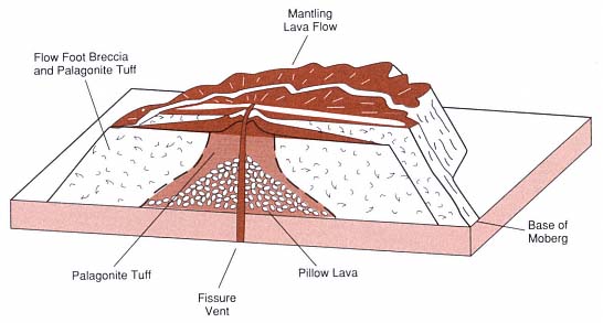
Fig. 6.16
Table mountain, or moberg, formed during eruption of basalt along a fissure under a glacier.
(Adapted from Jones, 1969.)
steam, water, and CO2 . The rocks, consisting of mostly lavas, a granophyre unit, and a dolerite sill, are intruded by multiple dikes. The two reservoirs are connected by a fault and/or a dike. Permeability in the upper zone is 10-11 m2 ; such permeabilities are reflected in the pressure increases and rises in water level during dike injection and eruption (Fig. 6.18). Pressure transients are not observed in the lower zone because the change is absorbed in the two-phase hydrothermal system.
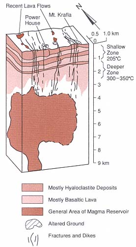
Fig. 6.17
Schematic cross-section of the Krafla geothermal
field and the underlying magma body
(Adapted from Stefánsson, 1981.)
Stefánsson (1981) noted that a severe mistake was made in constructing a power plant before the drilling was completed and the field was tested. As a result, the proposed maximum capacity of 35 MWe was not achieved. An eruption within the caldera also slowed construction work on the facility.
In Iceland, exploration techniques begin with detailed geologic mapping and dating of potential reservoir rocks. Determination of the eruption type is crucial; for example, by locating the vents and mapping facies within rocks erupted from a subglacial volcano, it is possible to evaluate not only the potential heat source, but also the location and extent of reservoir and caprocks. As noted earlier, pillow lavas are excellent reservoir rocks and the associated hyaloclastic carapaces are effective caprocks. All dikes and faults must be mapped for identification (or interpretation) of both thermal sources and potential aquicludes. After potential reservoir rocks have been evaluated at the surface, interpretative cross-sections can be prepared and evaluated by both geologist and hydrologist. An exploration drillhole can then be sited for further evaluation and temperature measurements. The primary targets in Iceland for direct-use purposes are highly permeable rocks that contain fluids with temperatures of > 100°C (Fridleifsson, 1978/79).
Geothermal Potential of Several Small Basaltic Islands
Surtsey
Much of what has been learned during the last 20 years concerning phreatomagmatic volcanism began with the mid-1960s submarine eruptions south of Iceland that eventually formed Surtsey, one of the Westmann Islands (Thorarinsson, 1965; 1966; 1967). The eruption, first noted on November 14, 1963, lasted more than 4 years and ended on June 5, 1967; this eruption formed an island of 2.8 km2 and an elevation of 174 m, which
is shown in Fig. 6.19. The early phases of activity were phreatomagmatic; much of the heat was lost in magma/sea water interactions that generated very energetic steam eruptions. The tephra deposited by these eruptions was barely warm to touch when was deposited as fallout and surges.
In later phases of activity, after a growing tuff ring denied the sea access to the vent, the main activity was lava fountaining, and lava flows that moved across the edges of the cone toward the sea. After activity ceased entirely, Stefánsson et al . (1985) drilled a 181-m-deep borehole on the cone at an elevation of 58 m. The tuff above sea level has a permeability of 1.2 × 10⁻¹⁰ m2 and the system within it is vapor-dominated. Below sea level, the estimated permeability of the basaltic tuffs is 4.1 × 10⁻¹³ m2 , and the tuffs are altered to palagonite (a mixture of smectite clays, zeolites, and iron oxides). No pillow lavas were encountered in this borehole, and the maximum temperature was 140°C at a depth of 104 m. Below this depth, near the contact between the sea floor and the base of the Surtsey cone, temperatures dropped to 40°C within altered tuffs that were cooled by sea water.
During the drilling operation, the borehole crossed a 13-m-thick dike at a depth of 80 m (Stefánsson et al ., 1985; Fig. 6.20). Most likely emplaced during the lava fountaining episodes late in the history of the cone, the dike can account for high heat flow within the cone. Fluids and heat from a tuff ring such as this one could be used for heating water but not for producing electricity; therefore, it is a limited, short-term resource unless the heat source were to be replenished by a new eruption.
Heimaey
Within sight of the new island of Surtsey is the small, populated island of Heimaey, which is an important Icelandic fishing community. On January 23, 1973, a north-north-east-trending fissure, located only 1 km east
Fig. 6.18
Interaction of the Krafla hydrothermal system with rising magma. Changes in the CO2
concentration and pH within wells KG-3 and KG-4 correspond to renewed eruptive activity.
(Adapted from Stefánsson, 1981.)
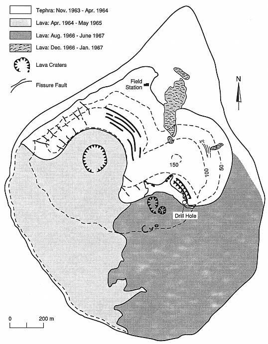
Fig. 6.19
Map of Surtsey volcano indicates the location of the 181-m-deep borehole.
(Adapted from Jakobsson and Moore, 1982.)
of the town center, opened over a length of 1200 m. Lava fountains occurred along the length of the fissure but were soon concentrated at one point (Williams and Moore, 1983). Within 2 days the lava fountaining had covered the island with ash and had constructed a 120-m-high scoria and spatter cone. Over the subsequent 2 weeks, lava fountaining decreased in intensity and a thick lava flow moved toward the edge of town. The 43- to 120-m-thick basaltic lava flow, at temperatures of 1030 to 1055°C, moved into the town and also threatened the harbor entrance.
To save the town and harbor, Icelandic officials were determined to stop the lava flow. Their method was to increase the lava's viscosity by spraying it with cold seawater and to construct a barrier along the flow margin. Seawater was sprayed onto the flow front and distributed across the flow surface at a rate of 1.7 m3 /s, cooling the flow to well below its solidus temperature. Barriers within the flow, which were formed by cooling, caused the flow to thicken. Over a 6-month period, the ~10 × 106 m3 of water sprayed onto the lava flows converted ~6.5 × 10⁶ m3 of molten lava into hot, but solid rock (Jonsson and Matthiasson, 1974; Williams and Moore, 1983).
The eruption ceased June 23, 1973, leaving a lava flow ~1.5 by 1.5 km and ~100 m thick that was overlain by ~5 m of scoria. The residents of Heimaey immediately began to examine ways to take advantage of this heat source. A district heating system was created and after a successful prototype system was tested, construction of a geothermal heating system began. Four 100- by 100-m areas were developed, each consisting of steamwells in the unconsolidated scoria overlying the lava flow and an overlying network of pipes that spray water onto the ground surface. The water seeps into the scoria and the lava flow, is converted to steam, and rises to the steamwell collectors (Fig. 6.21). Each well produces 2.5 MWthermal during normal operations (Björnsson, 1980; Williams and Moore, 1983). By 1982, the entire town was heated by steam from the lava flow.
Réunion Island in the Indian Ocean
The geothermal drilling project on the Island of Réunion in the western Indian Ocean provides an example of where one might not expect to find a hydrothermal system. Piton de la Fournaise, an active basaltic shield volcano on Réunion, was constructed on the southeast flank of an older shield volcano, Piton de Neiges. Fournaise has erupted about every 2 years during the last 250 years (Stieltjes, 1985). Broadly curving faults define a series of large blocks stepping down to the sea (Fig. 6.22); these features were interpreted by Stieltjes (1985) as a caldera and by Duffield et al . (1982) as large gravitational slumps. The faults flank a
Fig. 6.20
Temperature profiles and simplified lithologic
descriptions for the Surtsey borehole. Excess
heat encountered at ~80-m depth is probably
related to a 13-m-thick dike
complex in the core of the cone.
(Adapted from Jakobsson and Moore, 1982.)
Fig. 6.21
Diagram of the emplacement of shallow collectors (steamwells) in scoria deposits overlying a thick
basaltic lava flow from the 1973 eruption of Heimaey, Iceland. Water from surface pipes supplies
the recharge to the solidified, fractured lava flow, where steam is generated and collected in
a steamwell. This geothermal energy source is
successfully operating as a district-heating system.
(Adapted from Björnsson, 1980, and Williams and Moore, 1983.)
broad trough that slopes from the summit elevation of 2600 m to sea level. Kieffer et al . (1977), Duffield et al . (1982), and Stieltjes (1985) propose that the rift zones trend northeast, southeast, and northwest. Historic eruptions have occurred at vents in the summit caldera and along the flanking rifts. The Cratère Bory and Cratère Brûlant form a 1.2- by 0.7-km summit crater complex.
Two geothermal wells have been drilled on Réunion Island. One was sited on the east coast, in the outflow area of Piton de la Fournaise and the other on the older Piton des Neiges volcano. The Fournaise well, drilled on the shield flanks—inexplicably away from the active rifts—reached bottom in a dense gabbro intrusion and was cold. The second well reached rock at temperatures of 200°C but did not produce any fluids.
Geothermal heat sources in basaltic volcanoes rely on frequent but small eruptions. In contrast, along convergent plate boundaries and on the continents, eruptions are less frequent, but heat sources are shallow and large. Chapter 7 discusses the most common volcano type found at these convergent margins—composite cones.
Fig. 6.22
Piton de la Fournaise on Réunion Island in the Indian Ocean.
(a) Map of Piton de La Fournaise volcano Shaded areas indicate rift zones.
(Adapted from Duffield et al., 1982).
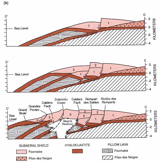
Fig. 6.22
(b) Diagrammatic cross-section C'—C. Features noted 1, 2, 3 refer to major periods of eruptive
activity. Gravity slump blocks from earlier stages are believed to be bounded by formerly active pairs
of northeast and southeast rift zones. A possible future slump block, shown with dashed line,
is located below fracture systems of the presently active rifts.
The position of the magma reservoir is speculative
(Adapted from Duffield et al., 1982).